Method and device for measuring impedance and power of plasma

A plasma and power technology, applied in the field of plasma measurement, can solve problems such as plasma absorption power monitoring, and achieve the effects of simple principles and steps, low cost and high accuracy

Inactive Publication Date: 2021-06-22
DALIAN UNIV OF TECH
View PDF3 Cites 2 Cited by
  • Summary
  • Abstract
  • Description
  • Claims
  • Application Information

AI Technical Summary

Problems solved by technology

To date, little scientific literature has been published on
[0006] Moreover, the commercial V-I sensor is designed for continuous wave (power on continuously) driven plasma, the equivalent impedance of continuous wave driven plasma discharge is constant, the sensor is only suitable for this typ

Method used


Image

  • Method and device for measuring impedance and power of plasma
  • Method and device for measuring impedance and power of plasma
  • Method and device for measuring impedance and power of plasma

Examples


Embodiment 1

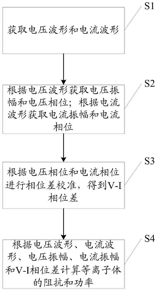
[0076] see figure 1 , the invention provides a method for measuring plasma impedance and power, comprising the following steps:

[0077] S1: Obtain voltage waveform and current waveform;

[0078] Specifically, waveform sampling is performed through a current probe and a voltage probe; waveform display and recording are performed through an oscilloscope.

[0079] S2: Obtain voltage amplitude and voltage phase according to the voltage waveform; obtain current amplitude and current phase according to the current waveform;

[0080] Specifically, the voltage waveform and the current waveform are divided into several sections with each sine cycle as a section;

[0081] Use MATLAB software (or other similar software) to perform fast Fourier analysis on the segmented voltage waveform and segmented current waveform, and obtain the voltage amplitude and voltage phase of each segment of the voltage waveform, and the current amplitude and sum of each segment of the current waveform. Cu...

Embodiment 2

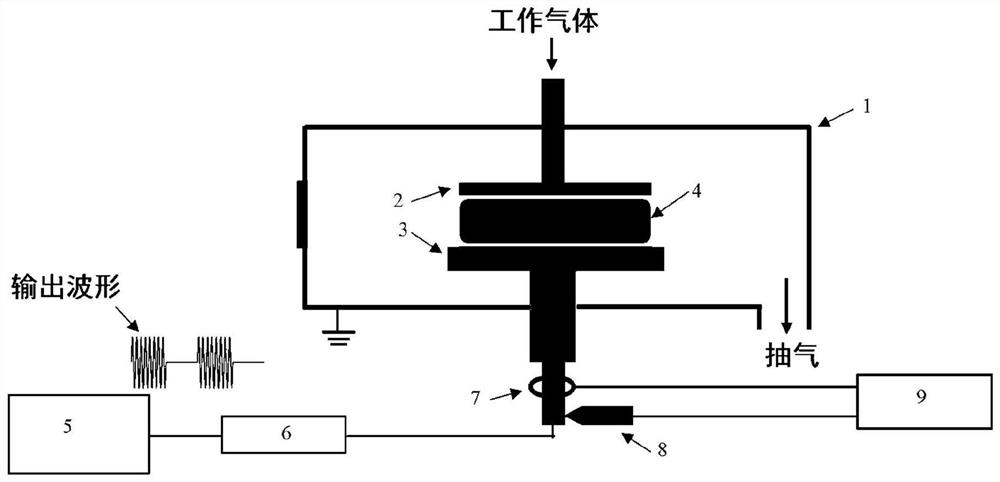
[0113] see figure 2 , the present invention also provides a device for measuring plasma impedance and power, comprising:

[0114] vacuum chamber;

[0115] The inside of the vacuum chamber includes an upper electrode and a lower electrode arranged in parallel, plasma is generated between the upper electrode and the lower electrode, and working gas enters the plasma region through the upper electrode; the outer wall and the upper electrode are grounded;

[0116] A pulsed radio frequency power supply, connected to the lower electrode through a matching circuit, for applying a radio frequency voltage;

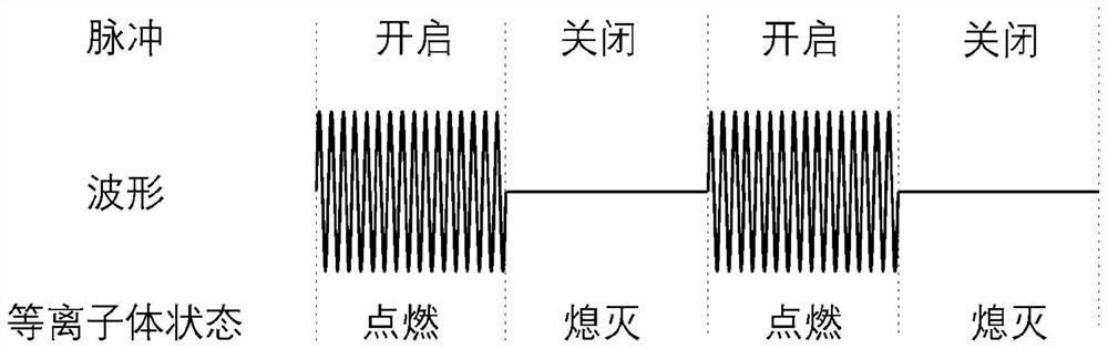
[0117] It should be noted that the waveform output by the pulsed radio frequency power supply is connected to the lower electrode after passing through the matching circuit. Under the excitation of this waveform (see image 3 ), the plasma is in an alternate state of "ignition-extinguishment-ignition", and the impedance and absorbed power of the plasma change drastically.

[...


PUM


Abstract

The invention relates to a method and a device for measuring impedance and power of plasma. The method comprises the following steps: acquiring a voltage waveform and a current waveform; acquiring a voltage amplitude and a voltage phase according to the voltage waveform; acquiring a current amplitude and a current phase according to the current waveform; performing phase difference calibration according to the voltage phase and the current phase to obtain a V-I phase difference; and calculating the impedance and power of the plasma according to the voltage waveform, the current waveform, the voltage amplitude, the current amplitude and the V-I phase difference. Aiming at the problems in the prior art, pulse modulation is carried out on a pulse radio frequency power supply, and the evolution process of radio frequency power and plasma impedance along with time is further obtained by prolonging the pulse turn-off time and calibrating the V-I phase difference; when the plasma is stable, stable-state (continuous wave-driven) plasma can absorb power.

Description

technical field [0001] The invention relates to the technical field of plasma measurement, in particular to a method and device for measuring plasma impedance and power. Background technique [0002] Plasma is a state of matter mainly composed of electrons, ions, and neutral particles, and is called the fourth state besides solid, liquid, and gaseous states. It exists widely in nature and is generally electrically neutral macroscopically. During the plasma discharge process, many chemically active ions and neutral free radicals are generated. In the processing of integrated circuit chips, nearly one-third of the processes are based on low-temperature plasma processing technology. [0003] In the process of surface treatment and modification of low-temperature plasma materials, etching is one of the most important processes. Using plasma etching, only one material is removed from the surface without affecting other materials, and only the material at the bottom of the tren...

Claims


Application Information

Patent Timeline
IPC IPC(8): H05H1/00
CPCH05H1/0081
Inventor 刘永新赵凯张权治王友年
Owner DALIAN UNIV OF TECH
Why Eureka
Try Eureka