
Image forming method

a technology of image forming and forming method, which is applied in the direction of electrographic process apparatus, instruments, developers, etc., can solve the problems of insufficient particle size distribution and shape uniformity of toner produced by such a process, and the cleaning of toner is often incomplete and other problems

Inactive Publication Date: 2005-03-01
KONICA CORP
View PDF1 Cites 6 Cited by
  • Summary
  • Abstract
  • Description
  • Claims
  • Application Information

AI Technical Summary

Benefits of technology

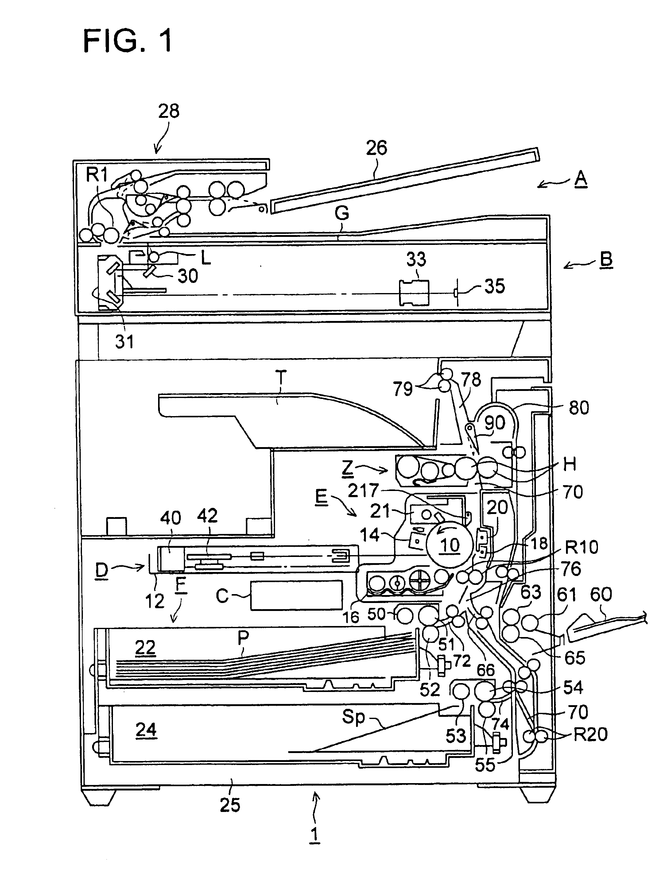
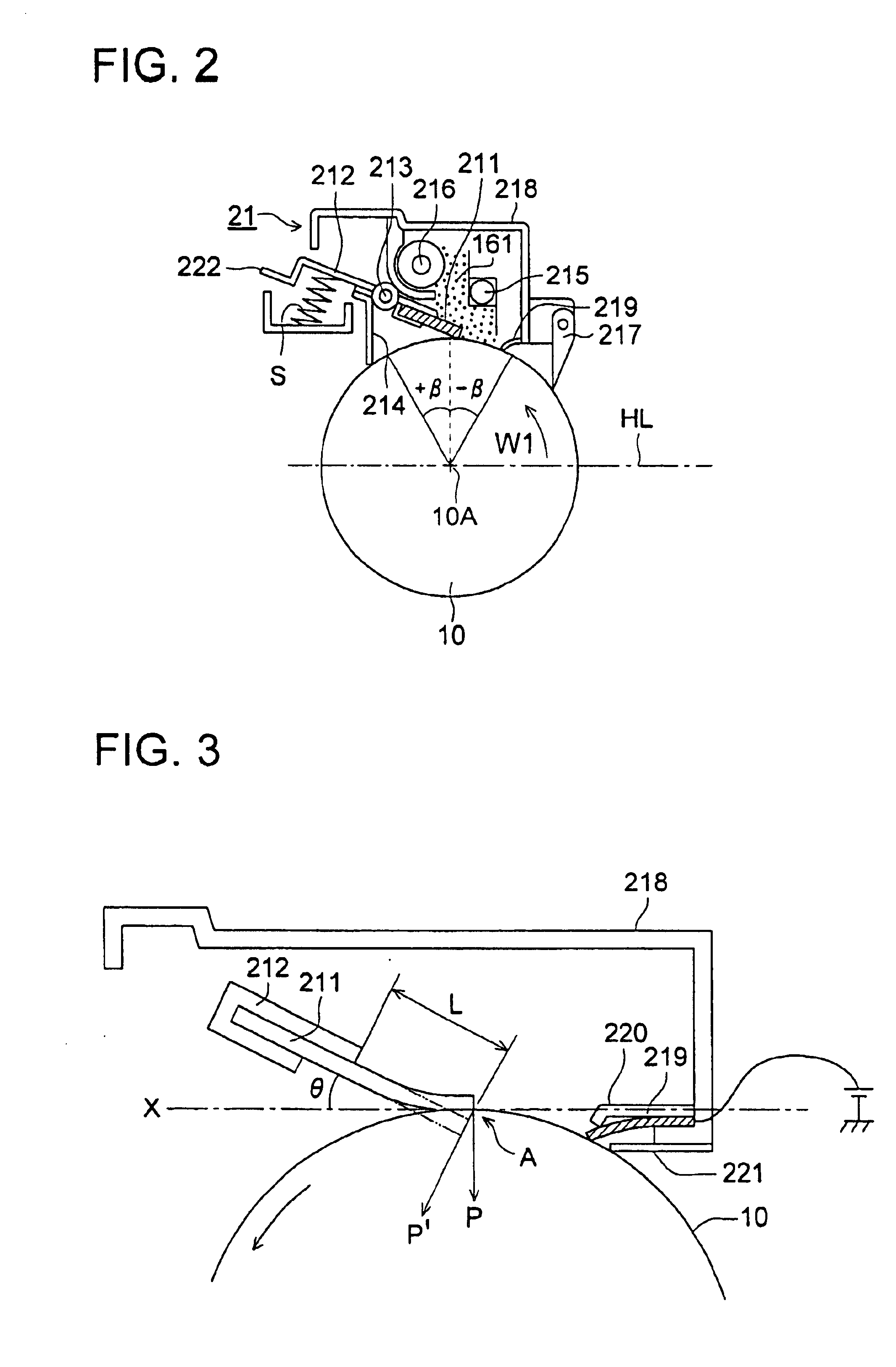
The object of the invention is to solve the above-mentioned problem and to provide an image forming method and an image forming apparatus by which incomplete cleaning occurred in the image forming apparatus having a cleaning blade arranged just above the cylindrical organic photoreceptor, hereinafter referred to as a cylindrical photoreceptor, an organic photoreceptor or a photoreceptor, is prevented so that the cleaning property is maintained for a long period and a sufficient electrophotographic image without any image defect can be obtained even when the polymerized toner is used.

Problems solved by technology

On the organic photoreceptor, various problems tend to be occurred on cleaning of the toner remained after transferring the toner to the image receiving material since the contact energy of the organic photoreceptor to the toner developing the latent image formed on the organic photoreceptor is large.
However, when the cleaning blade is contacted just above to the photoreceptor, incompleteness of cleaning is often occurred since the toner scraped off by the cleaning blade tends to be remained on the surface of the photoreceptor.
However, the toner produced by such the process is insufficient in the particle size distribution and the shape uniformity.
It is difficult to form an image with a sufficient quality by the use of such the toner.
A problem is newly raised when such the polymerized toner is used in an image forming apparatus having the organic photoreceptor.
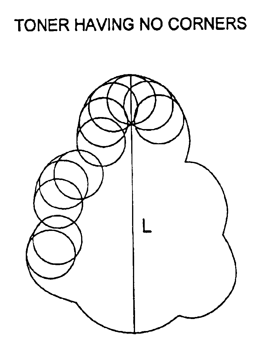
Namely, the cleaning tends to be incomplete since the shape of the toner particle is almost sphere and has a high attractive force to the organic photoreceptor surface.
Particularly, when the polymerized toner is applied to the image forming apparatus in which the cleaning device is arranged just above the cylindrical organic photoreceptor, very fine toner particles, by which no visible transferred image is formed, are slipped and passed through the cleaning blade and a charging device such as a charging wire or a charging roller is contaminated by such the very fine toner particles for a long period.
As a result of the contamination, unevenness in the halftone image is formed.

Method used


Image

  • Image forming method
  • Image forming method
  • Image forming method

Examples


examples

The present invention will now be detailed with reference to examples. In the followings, “parts” means “parts by weight”, unless otherwise specified.

Photoreceptor 1 was prepared as follows.

Preparation of Photoreceptor P1<Subbing layer>Titanium chelate compound TC-75030g(Matsumoto Seiyaku Co., Ltd.)Silane coupling agent KBM-50317g(Shin'etsu Kagaku Co., Ltd.)2-propanol150ml

The above coating liquid was coated on an electroconductive cylindrical substrate having a diameter of 100 mm so that the layer thickness is 0.5 μm.

<Charge generation layer>Y-type titanylphthalocyanine having the maximum peak of60gBragg angle 2θ(±0.2) at 27.7° in Cu-Kα X-ray diffractionspectrum2-butanone2000ml

The above-mentioned were mixed and dispersed for 10 hours by a sand mill to prepare a charge generation layer coating liquid. The coating liquid was coated on the foregoing subbing layer by an immersion coating method so as to form a charge generation layer with a thickness of 0.2 μm.

<Charge tra...


PUM


Abstract

A method of forming a toner image is disclosed. The photoreceptor is installed so that the center axis of the cylinder is to be almost horizontal, front edge of the cleaning blade is pressed against surface of the photoreceptor at the top, ratio of width of the photosensitive layer of the photoreceptor to length of the cylindrical electroconductive substrate is 80 / 100 to 99 / 100, and a number ratio of toner particles having a shape coefficient of 1.2 to 1.6 is at least 65 percent in the toner particles.

Description

FIELD OF THE INVENTIONThis invention relates to an image forming method and an image forming apparatus applicable to a copying machine or a printer each according to an electrophotographic method.BACKGROUND OF THE INVENTIONRecently an organic photoreceptor containing an organic photoconductive substance is widely used in an image forming apparatus according to an electrophotographic method. On the organic photoreceptor, various problems tend to be occurred on cleaning of the toner remained after transferring the toner to the image receiving material since the contact energy of the organic photoreceptor to the toner developing the latent image formed on the organic photoreceptor is large.An electrophotographic image forming apparatus having a cleaning device just above a cylindrical electrophotographic photoreceptor has been proposed in Japanese Patent Application No. 11-290755. Such the image forming apparatus has an advantage that the apparatus can be made compact. When a blade scr...

Claims


Application Information

Patent Timeline
Patent Type & Authority Patents(United States)
IPC IPC(8): G03G13/06G03G13/08G03G21/00G03G9/08G03G5/10G03G5/147G03G9/087G03G21/10
CPCG03G9/0819G03G21/0029G03G13/08G03G9/0827
Inventor OSHIBA, TAKEOMOCHIZUKI, FUMITAKASHIDA, KAZUHISA
Owner KONICA CORP
Learn More