Weighing sensor with calibration weight

a weighing sensor and calibration technology, applied in the field of weighing sensors with calibration weight, can solve the problems of reducing the overall height of the weighing sensor, restricting the design options, and occupying a large spa

Inactive Publication Date: 2005-03-01
SARTORIUS LAB INSTR GMBH & CO KG
View PDF13 Cites 23 Cited by
  • Summary
  • Abstract
  • Description
  • Claims
  • Application Information

AI Technical Summary

Benefits of technology

[0007]One object of the invention is to obviate the space problems in the space between the load sensor, t...

Problems solved by technology

However, they cause substantial space problems in the space between the load sensor, the base fixed to the housing and the two arms.
As a result, they significantly restrict the design options for the lever sy...

Method used


Image

  • Weighing sensor with calibration weight
  • Weighing sensor with calibration weight

Examples


Embodiment Construction

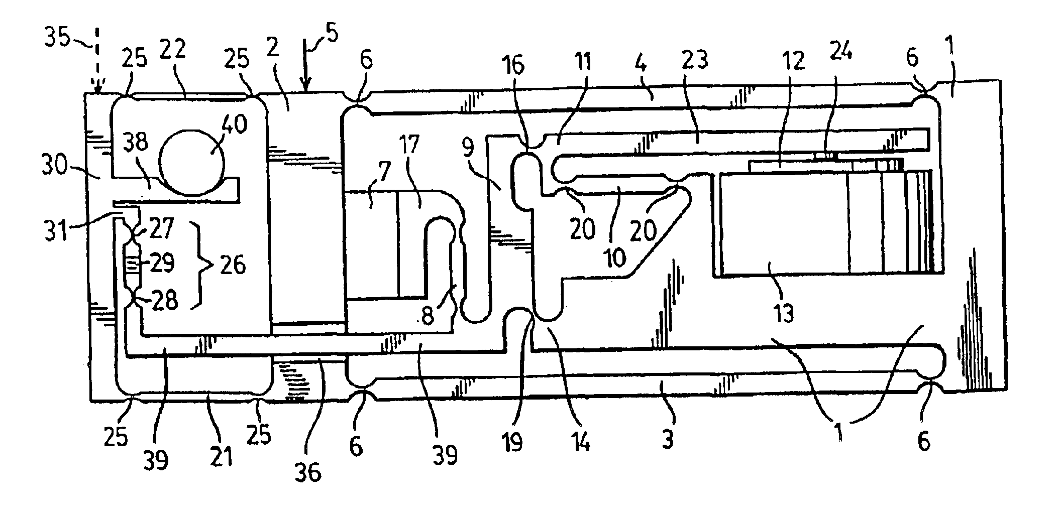
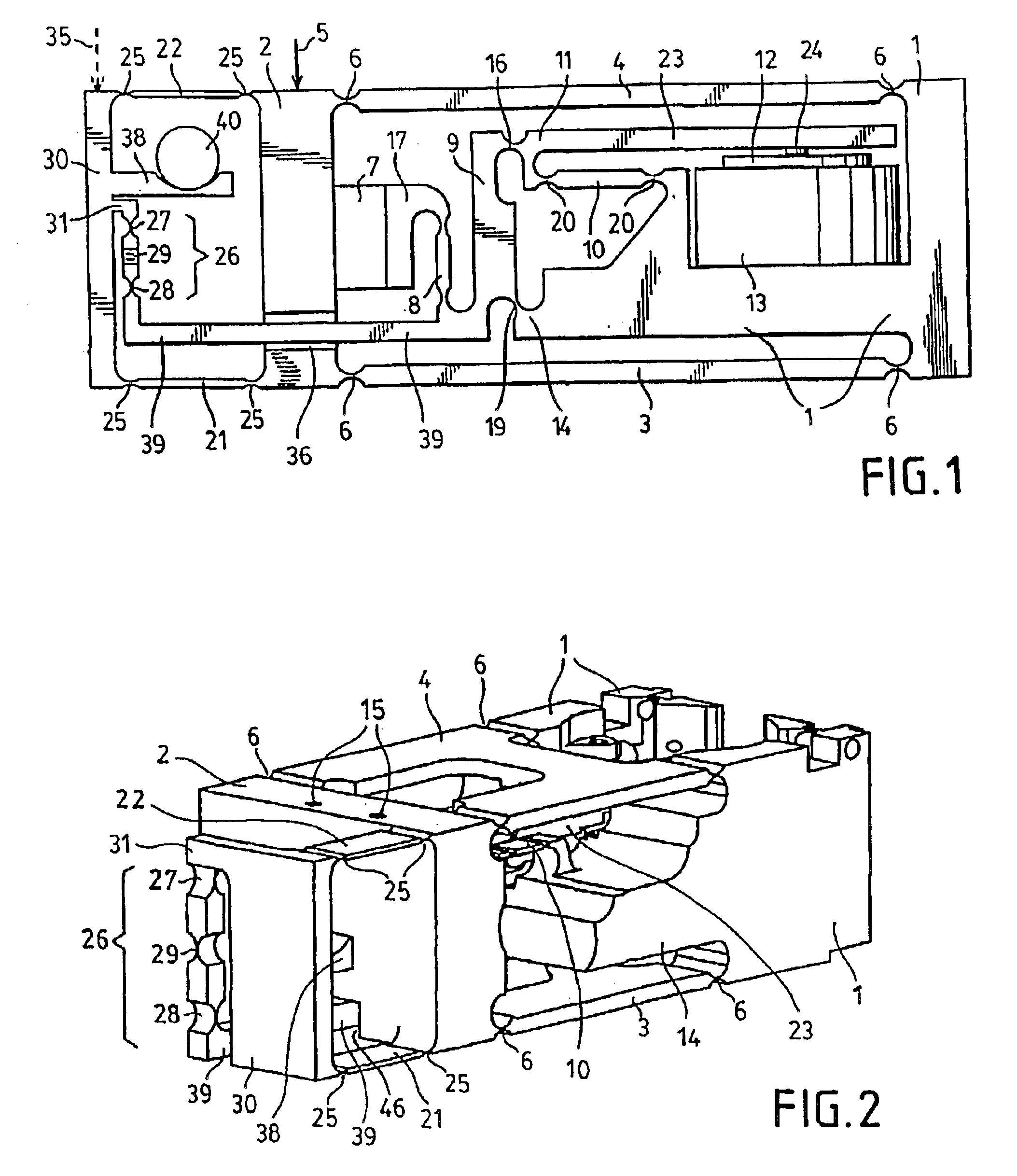
[0014]FIG. 1 shows a schematic side view of the weighing sensor illustrating the weighing sensor's basic structure. The figure shows a load sensor 2, which is connected to a basic body 1 fixed to the housing via an upper arm 4 and a lower arm 3 in a parallel motion arrangement. The numeral 6 identifies the articulation points of the arms. The weighing pan (not shown) is mounted to the load sensor 2. A vertical arrow 5 indicates the force exerted by the material being weighed. The weight force of the material being weighed is transmitted from a projection 7 / 17 of the load sensor 2 via a first, vertical force transmission element 8 to a rectangular lever 9. The rectangular lever 9 is supported on a projection 14 of the basic body 1 by a thin spot 19. The short, horizontal lever arm of the rectangular lever 9 equals the horizontal distance between the force transmission element 8 and the thin spot 19. The long, vertical lever arm equals the vertical distance between the thin spot 19 an...


PUM


Abstract

A weighing sensor including a base (1) fixed to a housing, a load sensor (2) connected to the base in a displaceable manner via two arms (3, 4), a lever system (8 . . . 11) having at least one lever and transmitting the load acting on the load sensor to a transducer (12, 13), and a built-in calibration weight (40) which may be lowered onto a support region (30/38) for checking and/or calibrating the sensitivity of the weighing sensor. The support region is guided in a parallel manner by two additional arms (21, 22) and is connected to a lever (9/39) of the lever system (8 . . . 11) via a coupling element (26). Relatively large loads on the weighing sensor may be simulated with relatively small calibration weights, without the need for complicated lifting devices. The two additional arms (21, 22) are connected on the one hand to the support region (30/38) and on the other hand to the load sensor (2) and are located on the side of the load sensor (2) opposite from the lever system (8 . . . 11).

Description

[0002]This is a Continuation of International Application PCT / EP01 / 12487, with an international filing date of Oct. 29, 2001, which was published under PCT Article 21(2) in German, and the disclosure of which is incorporated into this application by reference.FIELD OF AND BACKGROUND OF THE INVENTION[0003]The invention relates to a weighing sensor with a base that is fixed to the housing, a load sensor connected to the base in a displaceable manner using two arms, a lever system that has at least one lever and that transmits the load acting on the load sensor to a transducer, and a built-in calibration weight that can be lowered onto a support region to check and / or calibrate the sensitivity of the weighing sensor. The support region is parallel-guided using two additional arms and is connected to a lever of the lever system using a coupling element.[0004]Weighing sensors of this type are known, for instance, from German Patent Specification DE 196 05 087 C2. They are preferably used...

Claims


Application Information

Patent Timeline
IPC IPC(8): G01G21/24G01G23/01
CPCG01G21/244G01G23/012
Inventor KUHLMANN, OTTOCAPELLE, THORSTENFLEISCHER, PETERHELMSEN, FRIEDRICHERBEN, DETLEVMUELLER, RUDOLF
Owner SARTORIUS LAB INSTR GMBH & CO KG
Why Eureka
Try Eureka