Motor control apparatus and motor control method

a motor control and control apparatus technology, applied in the direction of motor/generator/converter stopper, dynamo-electric gear control, dynamo-electric converter control, etc., can solve the problems not being able to converge the actual current, etc., and achieve the effect of reducing the response of the current control system

Inactive Publication Date: 2005-03-01
NISSAN MOTOR CO LTD
View PDF13 Cites 31 Cited by
  • Summary
  • Abstract
  • Description
  • Claims
  • Application Information

AI Technical Summary

Benefits of technology

However, factors such as the level of the source voltage and the output limit at the invertor set upper and lower limits on the level of a voltage that can be applied to the motor, and the 3-phase AC voltage command value calculated through the current control circuits described above may be higher or lower than the invertor output voltage. In such a case, it is not possible to converge the actual currents to the command values at the fundamental current control circuit and the higher harmonic current control circuit. If the control implemented by the current control circuits includes integral control in this situation, the deviations of the actual currents relative to the command values, i.e., the current control errors, are continuously integrated, which greatly reduces the response of the current control systems.

Problems solved by technology

In such a case, it is not possible to converge the actual currents to the command values at the fundamental current control circuit and the higher harmonic current control circuit.
If the control implemented by the current control circuits includes integral control in this situation, the deviations of the actual currents relative to the command values, i.e., the current control errors, are continuously integrated, which greatly reduces the response of the current control systems.

Method used


Image

  • Motor control apparatus and motor control method
  • Motor control apparatus and motor control method
  • Motor control apparatus and motor control method

Examples


first embodiment

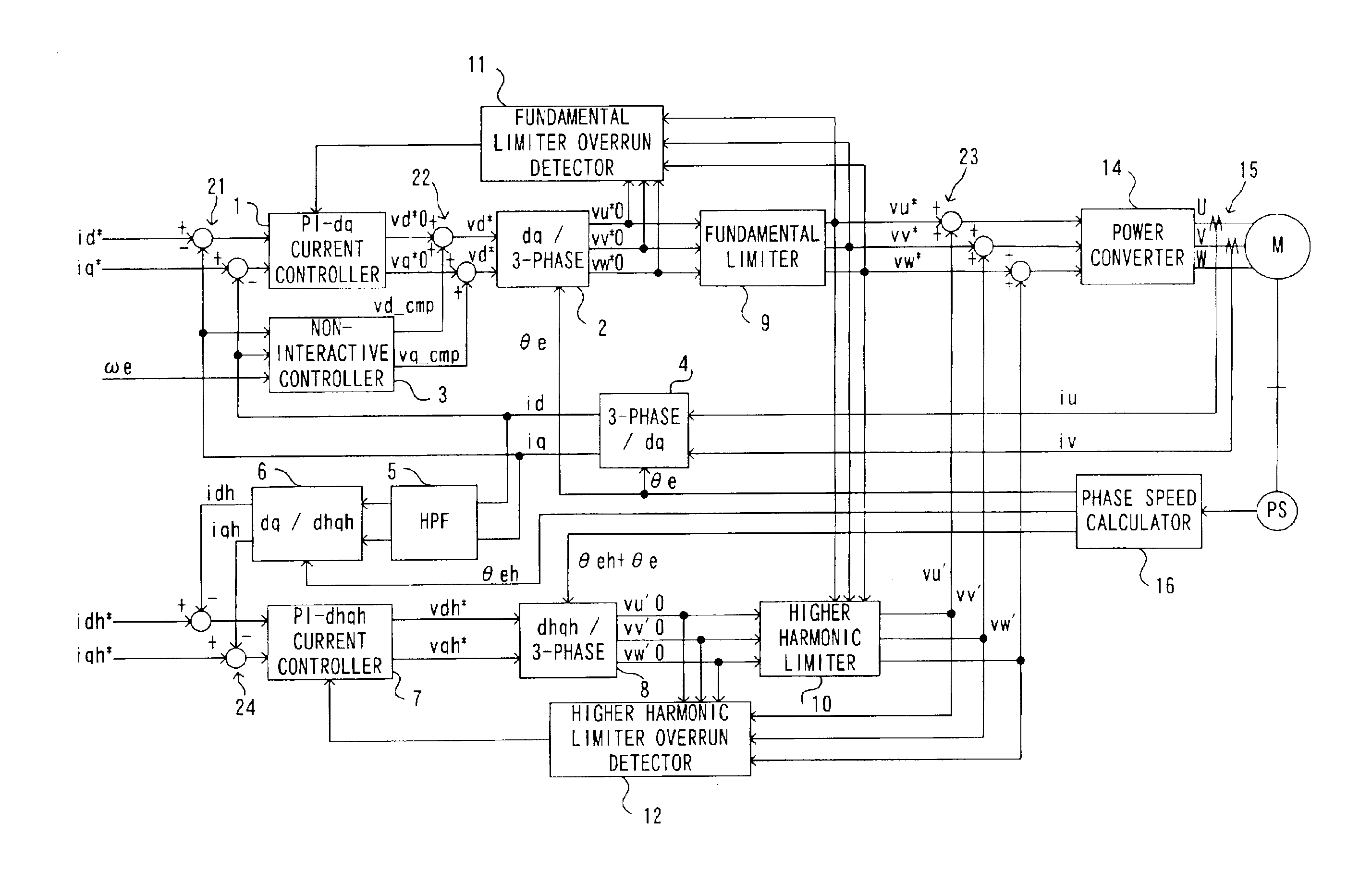
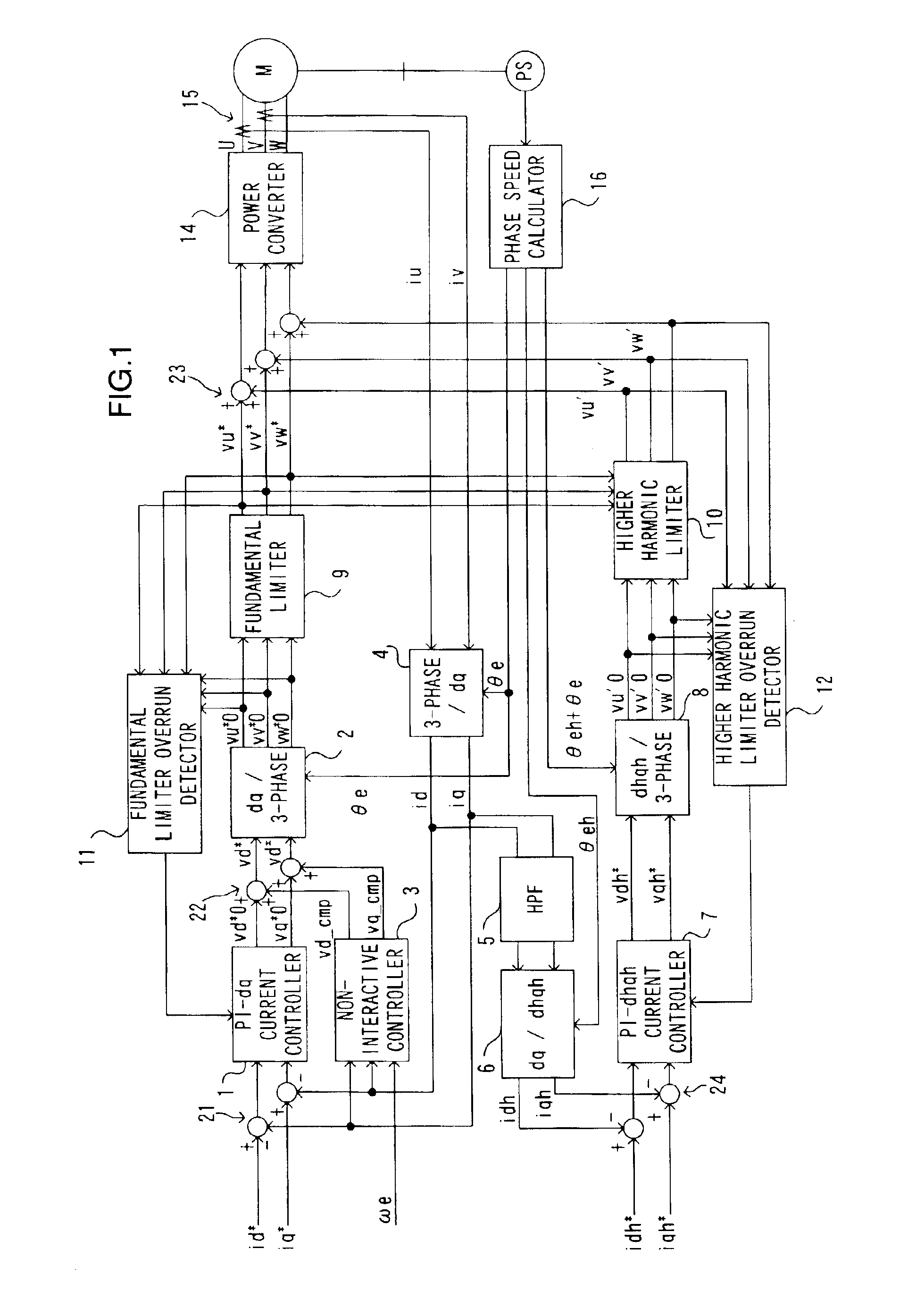
FIG. 1 is a control block diagram showing the structure of the motor control apparatus achieved in the first embodiment. The motor control apparatus in the first embodiment includes a fundamental current control circuit and a higher harmonic current control circuit. The fundamental current control circuit controls the fundamental components in motor currents iu, iv and iw in a dq-axis coordinate system which rotates in synchronization with the motor rotation. The higher harmonic current control circuit controls the higher harmonic components contained in the motor currents iu, iv and iw in an orthogonal coordinate system (hereafter referred to as a higher harmonic coordinate system or a dhqh-axis coordinate system) which rotates with the frequency of a higher harmonic component of a predetermined order manifesting when the motor currents iu, iv and iw are controlled through the fundamental current control circuit alone. In other words, the dhqh-axis coordinate system is a higher har...

second embodiment

In the motor control apparatus achieved in the first embodiment, the integral gains used in the fundamental current control are set to 0 if 3-phase fundamental voltage command values output from the fundamental current control circuit fall outside the ranges set by the upper and lower limit values and the integral gains used in the higher harmonic current control are set to 0 if the 3-phase higher harmonic voltage command values output from the higher harmonic current control circuit fall outside the ranges set by the upper and lower limit values. In the motor control apparatus achieved in the second embodiment, on the other hand, if the 3-phase AC voltage command values fall outside ranges set by the upper and lower limit values in the fundamental current control circuit and the higher harmonic current control circuit, the fundamental current command values and the higher harmonic current command values are reduced in correspondence to the extents of the deviations.

FIG. 4 is a cont...

third embodiment

In the motor control apparatuses achieved in the first and second embodiments described above, the limit processing is implemented on the voltage command values in the 3-phase AC coordinate system. In the motor control apparatus achieved in the third embodiment, limit processing is implemented on the voltage command values in a 2-phase AC coordinate system (hereafter referred to as an αβ-axis coordinate system).

FIG. 5 is a control block diagram showing the structure of the motor control apparatus achieved in the third embodiment. It is to be noted that the following explanation focuses on the differences from the structures shown in FIGS. 1 and 4 by assigning the same reference numerals to components similar to those in FIGS. 1 and 4.

In the fundamental current control circuit, a dq / 2-phase converter 2B executes a coordinate transformation to respectively convert the d-axis voltage command value vd* and the q-axis voltage command value vq* to voltage command values vα*0 and vβ*0 in t...


PUM


Abstract

Limits are imposed on a fundamental voltage command value calculated at a fundamental current control circuit that controls a fundamental component of a 3-phase AC motor current in a dq-axis coordinate system rotating in synchronization with the rotation of the 3-phase AC motor by using predetermined limit values and limits are imposed on a higher harmonic voltage command value calculated in an orthogonal coordinate system (a higher harmonic coordinate system) rotating at a frequency set to an integral multiple of the frequency of the fundamental component in the 3-phase AC motor current by using a predetermined limit values. The voltage command values resulting from the limit processing are added together and a voltage corresponding to the sum is applied to the AC motor for drive control.

Description

BACKGROUND OF THE INVENTION1. Field of the InventionThe present invention relates to a motor control apparatus and a motor control method and, more specifically, it relates to a technology whereby a higher harmonic current flowing through a 3-phase AC motor is reduced.2. Description of the Related ArtThe applicant of the present invention proposed a motor control apparatus that reduces a higher harmonic current flowing through a 3-phase AC motor in Japanese Patent Application No. 2000-356117. The motor control apparatus, which includes a fundamental current control circuit that controls a fundamental current in a dq-axis coordinate system rotating in synchronization with the motor rotation and a higher harmonic current control circuit that controls a higher harmonic current in a dhqh coordinate system rotating at a frequency set to an integral multiple of the frequency of the fundamental current, controls a current flowing to the 3-phase AC motor. The fundamental current control cir...

Claims


Application Information

Patent Timeline
Patent Type & Authority Patents(United States)
IPC IPC(8): H02P21/00H02P6/08H02P6/06H02P6/17H02P6/28H02P21/05H02P21/22H02P23/04H02P25/026H02P27/04
CPCH02P21/0035H02P21/22
Inventor YOSHIMOTO, KANTAROKITAJIMA, YASUHIKO
Owner NISSAN MOTOR CO LTD
Why Eureka
Try Eureka