pi-Type band pass filter

Inactive Publication Date: 2005-03-01
FORMOSA TELETEK CORP
View PDF4 Cites 6 Cited by
  • Summary
  • Abstract
  • Description
  • Claims
  • Application Information

AI Technical Summary

Benefits of technology

The improved π-type band pass filter disclosed by the present invention uses a π-type inductor to make the coupling coefficient of the filter related to the first serial inductor, the first parallel inductor, and the compensating inducto

Problems solved by technology

However, as the filter is miniaturized, the dielectric coupling in the circuits is likely to introduce additional noises.
It is difficult to design a high-selectivity (narrow band) band pass filter.
On the other hand, as the distance between the two resonant inductors increases, the dielectric may incorporate more noises, which may greatly affect the characteristics of the filter.
However

Method used


Image

  • pi-Type band pass filter
  • pi-Type band pass filter
  • pi-Type band pass filter

Examples


Embodiment Construction

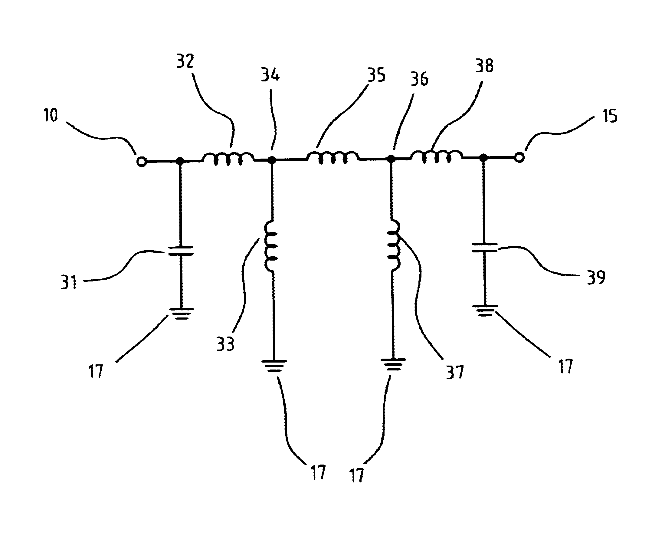
FIG. 3 shows a π-type band pass filter of the present invention. Input signals enter the filter from the input signal end 10. A first resonant capacitor 31 is placed between input signal end 10 and ground 17, and a first serial inductor 32 is placed between input signal end 10 and a first junction 34. A first parallel inductor 33 is placed between first junction 34 and ground 17. A compensating inductor 35 is placed between first junction 34 and a second junction 36. A second parallel inductor 37 is placed between second junction 36 and ground 17. A second serial inductor 38 is placed between second junction 36 and a signal output end 10. A second resonant capacitor 39 is placed between signal output end 15 and ground 17. The signal output end 15 outputs signals. First and second resonant capacitors 31, 39 have the same capacitance, first and second serial inductors 32, 38 have the same inductance, and first and second parallel inductors 33, 37 have the same inductance.

When signals ...


PUM


Abstract

An improved band pass filter of π-type inductor is disclosed, which utilizes the serial inductor in the π as a compensating inductor, which can lower the coupling coefficient of the band pass by adjusting the inductance ratio of the compensating inductor to that of the two parallel grounded inductors. Therefore, the coupling coefficient is lowered by adjusting the inductance of the π-type inductors, avoid noise generation, and obtain optimal band pass characteristics, while miniaturizing the filter.

Description

FIELD OF THE INVENTIONThe present invention relates to a band pass filter and, more particularly, to an apparatus of π-type band pass filer, utilizing a π-type inductor.BACKGROUND OF THE INVENTIONThe coupling coefficient Km represents the selectivity of signals in the frequency domain. The lower the coupling coefficient of a circuit, the higher the circuit's selectivity of signals.In the design of a band pass filter using an inductor coupling resonant circuit, the coupling is usually realized with neighboring and parallel inductors. Therefore, it is necessary to have a larger space in order to obtain a smaller coupling coefficient. However, as the filter is miniaturized, the dielectric coupling in the circuits is likely to introduce additional noises. It is difficult to design a high-selectivity (narrow band) band pass filter. Furthermore, the coupling coefficients of the conventional filters are solely determined by the coupling inductance of parallel inductors. When designing mini...

Claims


Application Information

Patent Timeline
IPC IPC(8): H03H7/01
CPCH03H7/0115
Inventor WANG, TAI-CHANGTUNG, WEI-SHIN
Owner FORMOSA TELETEK CORP
Why Eureka
Try Eureka