
Sound signal enhancement device

a sound signal and enhancement device technology, applied in the field of sound signal enhancement devices, can solve the problems of inability to collect a small amount of learning data, large amount of learning data requires a great amount of time and cost, and the learning of a neural network does not work well, so as to achieve the effect of high-quality enhancement of sound signals

Active Publication Date: 2020-08-11
MITSUBISHI ELECTRIC CORP
View PDF25 Cites 0 Cited by
  • Summary
  • Abstract
  • Description
  • Claims
  • Application Information

AI Technical Summary

Benefits of technology

The present invention provides a sound signal enhancement device that can improve the accuracy of signals with less frequency of occurrence, such as voice not normally uttered and other abnormal sounds. By using a neural network and a small amount of learning data, the device can weight the features of a target signal and a supervisory signal, and obtain a high-quality enhancement signal. This learning process is faster and more efficient, making it possible to improve the accuracy of sound signal enhancement even with limited data.

Problems solved by technology

However, with regard to signals having less frequency in occurrence of a target signal or noise, such as voice not normally uttered such as screams or yells, sounds accompanied by natural disasters such as an earthquake, disturbance sound unexpectedly generated such as gunshots, abnormal sounds or vibrations presaging a failure of a machine, or warning sounds output when a machine error occurs, it is only possible to collect a small amount of learning data.
This is because a large number of constraints are imposed such as that the collection of a large amount of learning data requires a great amount of time and cost, or that a manufacturing line is needed to stop in order to issue a warning sound.
Therefore, in the conventional method as disclosed in Patent Literature 1, learning of a neural network does not work well due to the insufficient learning data, and thus there is a problem that accuracy of the enhancement may deteriorate.

Method used


Image

  • Sound signal enhancement device
  • Sound signal enhancement device
  • Sound signal enhancement device

Examples


embodiment 1

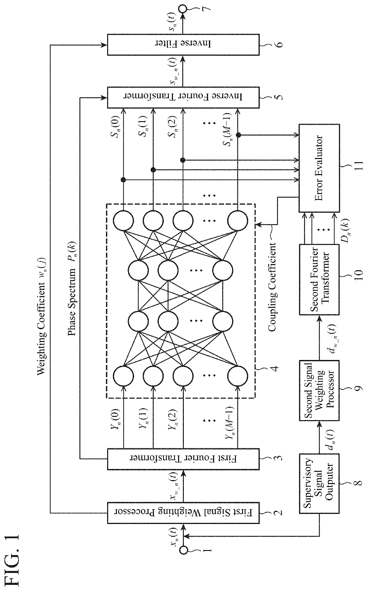
[0020]FIG. 1 is a block diagram illustrating a schematic configuration of a sound signal enhancement device according to Embodiment 1 of the present invention. The sound signal enhancement device illustrated in FIG. 1 includes a signal input part 1, a first signal weighting processor 2, a first Fourier transformer 3, a neural network processor 4, an inverse Fourier transformer 5, an inverse filter 6, a signal output part 7, a supervisory signal outputer 8, a second signal weighting processor 9, a second Fourier transformer 10, and an error evaluator 11.

[0021]An input to the sound signal enhancement device may be a sound signal such as speech sound, music, signal sound, or noise read through a sound transducer like a microphone (not shown) or a vibration sensor (not shown). These sound signals are converted from analog to digital (A / D conversion), sampled at a predetermined sampling frequency (for example, 8 kHz), and divided into frame units (for example, 10 ms) to generate signals ...

embodiment 2

[0081]In the foregoing Embodiment 1, the weighting process of the input signal is performed in the time waveform domain. Alternatively, it is possible to perform the weighting process of an input signal in the frequency domain. This configuration will be described as Embodiment 2.

[0082]FIG. 7 illustrates an internal configuration of a sound signal enhancement device according to the Embodiment 2. In FIG. 7, configurations different from those of the sound signal enhancement device of the Embodiment 1 illustrated in FIG. 1 includes a first signal weighting processor 12, an inverse filter 13, and a second signal weighting processor 14. Other configurations are similar to those of the Embodiment 1, and thus the same symbol is provided to corresponding parts, and descriptions thereof will be omitted.

[0083]The first signal weighting processor 12 is a processing part that receives a power spectrum Yn(k) output from a first Fourier transformer 3, performs in the frequency domain a process ...

embodiment 3

[0090]In the foregoing Embodiments 1 and 2 described above, a power spectrum being a signal in the frequency domain is input to and output from the neural network processor 4. Alternatively, it is possible to input a time waveform signal. This configuration will be described as Embodiment 3.

[0091]FIG. 8 illustrates an internal configuration of a sound signal enhancement device according to the present embodiment. In FIG. 8, an operation of an error evaluator 15 is different from that in FIG. 1. Other configurations are similar to those in FIG. 1, and thus the same symbols are provided to corresponding parts, and descriptions thereof will be omitted.

[0092]A neural network processor 4 receives weighted input signals xw_n(t) output from the first signal weighting processor 2, and outputs, similar to the neural network processor 4 of the foregoing Embodiment 1, enhancement signals sn(t) in which a target signal is enhanced.

[0093]The error evaluator 15 calculates a learning error Et thro...


PUM


Abstract

A first signal weighting processor outputs a weighted signal obtained by performing a weighting on part of an input signal representing a feature of a target signal included in the input signal. A neural network processor outputs an enhancement signal for the target signal by using a coupling coefficient. An inverse filter cancels the weighting on the feature representation of the target signal in the enhancement signal. A second signal weighting processor outputs a weighted signal obtained by performing a weighting on part of a supervisory signal representing a feature of a target signal. An error evaluator output a coupling coefficient to have a value indicating that a learning error between the weighted signal output from the second signal weighting processor and the output signal of the neural network processor is less than or equal to a set value.

Description

TECHNICAL FIELD[0001]The present invention relates to a sound signal enhancement device for enhancing a target signal, which has been included in an input signal, by suppressing unnecessary signals other than the target signal.BACKGROUND ART[0002]Along with a progress of technology of digital signal processing in recent years, voice communication through mobile phones in the outdoors, hands-free voice communication within automobiles, and hands-free operation by speech recognition are widely spread. Automatic monitoring systems have been also developed, which capture and detect screams or yells of people or abnormal sounds or vibrations generated by machines.[0003]Devices that implement the foregoing functions are often used in a noisy environment, such as the outdoors or plants, or in a highly echoing environment where sound signals generated by speakers or other devices reach a microphone. Thus, unnecessary signals, such as background noise or sound echo signals, are also input to...

Claims


Application Information

Patent Timeline
Patent Type & Authority Patents(United States)
IPC IPC(8): G10L21/0264G10L21/0208G10L25/30G10L21/0232
CPCG10L21/0264G10L21/0232G10L21/0208G10L25/30
Inventor FURUTA, SATORU
Owner MITSUBISHI ELECTRIC CORP
Learn More