Airport map system with compact feature data storage

Inactive Publication Date: 2005-03-01
SMITHS AEROSPACE INC
View PDF33 Cites 77 Cited by
  • Summary
  • Abstract
  • Description
  • Claims
  • Application Information

AI Technical Summary

Benefits of technology

To address the goals stated above and other goals, the inventive airport map system includes a unique data storage method and structure that reduces th

Problems solved by technology

A pilot can become confused or lost amid the many runways, taxiways, ramps, and buildings.
The problem is more significant at large airports and is particularly significant at night or in low visibility conditions when the multitude of lights can make it more difficult to taxi to the desired destination.
Efficient taxi operations save time and money.
Airports are becoming more crowded.
Aircraft often spend considerable time taxiing between runways and gates.
In addition, a wrong turn or navigation blunder can cause delays for other aircraft at the airport.
An obstacle for the practical implementation of an avionics systems to aid the pilot in finding his way safely to the active t

Method used


Image

  • Airport map system with compact feature data storage
  • Airport map system with compact feature data storage
  • Airport map system with compact feature data storage

Examples


Example

Reference will now be made in detail to the present preferred embodiments of the invention, examples of which are illustrated in the accompanying drawings. Wherever possible, the same reference numerals will be used throughout the drawings to refer to the same or like parts.

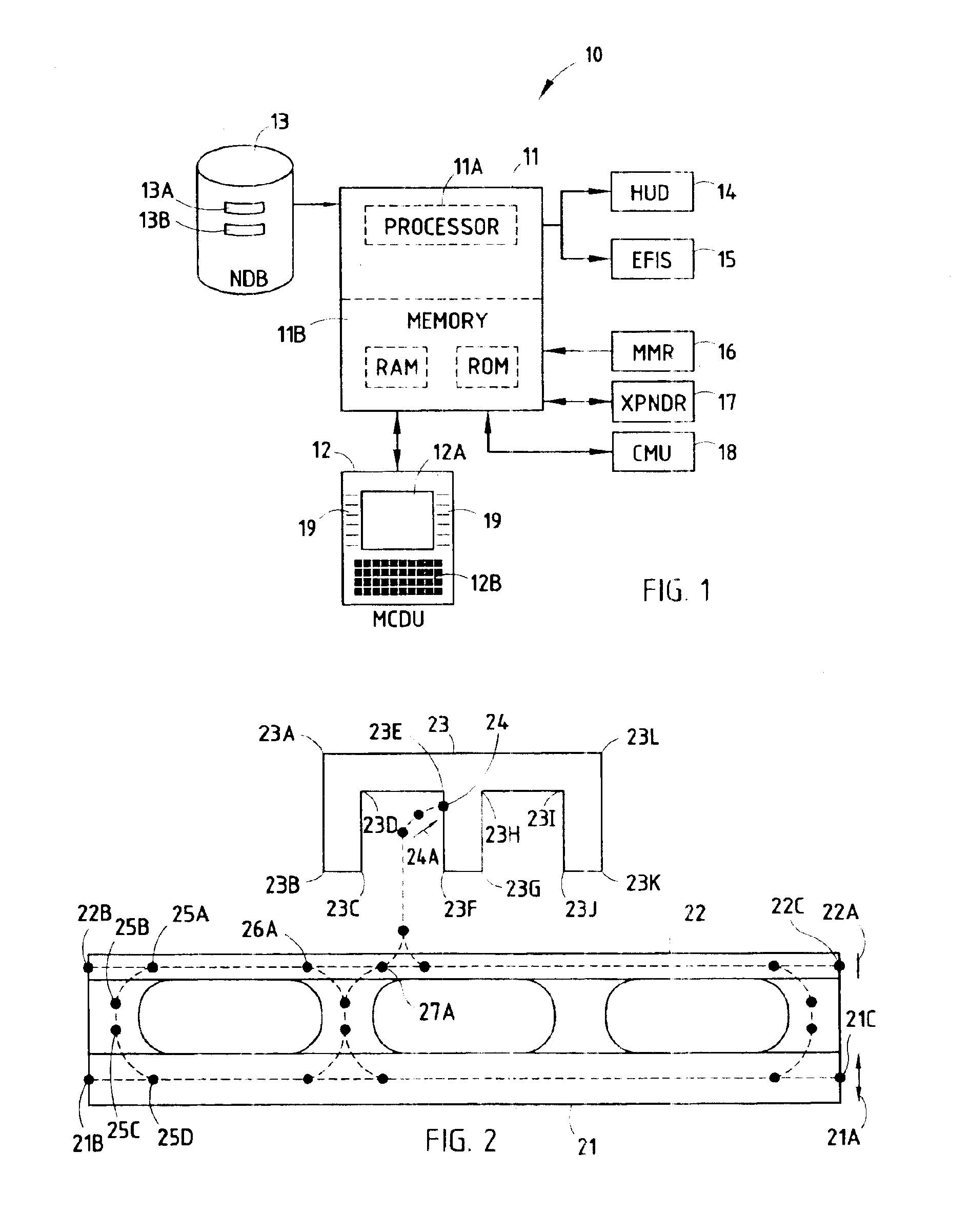
Referring to FIG. 1, an exemplary embodiment of the taxi planning system according to the present invention is shown, and is designated generally throughout by reference numeral 10. The components of the taxi planning system of the present invention will first be briefly described and then described in detail. The most common use for the taxi planning system 10 is as an integrated element in the FMS of an aircraft, such as a commercial passenger or cargo jet, and therefore the following discussion will describe the invention in relation to such an application.

The taxi planning system 10 according to the invention is shown with related aircraft systems. Any and all of the aircraft systems can comprise the taxi pla...


PUM


Abstract

An airport map display system for an aircraft displays the airport paved surfaces and structures to a pilot or crew member. The system displays runways, taxiways, connectors, ramps, gates, and buildings. Hold and yield points may also be displayed. A compact set of specific data points and associated pavement width values is used to store unique data for each airport.

Description

BACKGROUND OF THE INVENTION1. Field of the InventionThe present invention relates to aircraft surface guidance systems (SGS) and, in particular, to a method to format and store data regarding the paved surfaces, gates, and buildings of an airport and to display a map of the airport to the pilot.2. Technical BackgroundThere is considerable interest in enhancing the field of surface guidance for aircraft. After an aircraft lands at an airport the next step is to taxi the aircraft to a desired destination such as a passenger loading / unloading gate. A pilot can become confused or lost amid the many runways, taxiways, ramps, and buildings. The problem is more significant at large airports and is particularly significant at night or in low visibility conditions when the multitude of lights can make it more difficult to taxi to the desired destination.Efficient taxi operations save time and money. Airports are becoming more crowded. Aircraft often spend considerable time taxiing between ru...

Claims


Application Information

Patent Timeline
IPC IPC(8): G01C23/00G09B29/00B64D45/00G08G5/00
CPCG01C23/005G08G5/065G08G5/0021
Inventor WALTER, RANDY L.
Owner SMITHS AEROSPACE INC
Why Eureka
Try Eureka