Fluid parameter measurement in pipes using acoustic pressures

a technology of fluid parameter and pipe, which is applied in the direction of instruments, heat measurement, specific gravity measurement, etc., can solve the problems of inability of instruments to determine the propagation velocity, inability to precisely control the acoustic source, and inability to accurately measure the propagation velocity, etc., to achieve less sensitive to static shifts (or errors) in sensing and improve the reliability of measurement.

Inactive Publication Date: 2005-03-08
WEATHERFORD TECH HLDG LLC
View PDF101 Cites 125 Cited by
  • Summary
  • Abstract
  • Description
  • Claims
  • Application Information

AI Technical Summary

Benefits of technology

The present invention provides a significant improvement over the prior art by providing a measurement of the speed of sound (amix) in a mixture of one or more fluids within a pipe (where a fluid is defined as a liquid or a gas) by using an axial array of acoustic (or ac, dynamic, unsteady, or time varying) pressure measurements along the pipe. An explicit acoustic noise source is not required because the background acoustic noises within the pipe (or fluid therein) will likely provide sufficient excitation to allow a characterization of the speed of sound of the mixture by mere passive acoustic listening.
The present invention allows the speed of sound to be determined in a pipe independent of pipe orientation, i.e., vertical, horizontal, or any orientation therebetween. Also, the invention does not require any disruption to the flow within the pipe (e.g., an orifice or venturi). Further, the invention uses ac (or unsteady or dynamic) pressure measurements as opposed to dc (static) pressure measurements and is therefore less sensitive to static shifts (or errors) in sensing. Furthermore, if harsh environment fiber optic pressure sensors are used to obtain the pressure measurements, such sensors eliminate the need for any electronic components down-hole, thereby improving reliability of the measurement.
Also, a strain gauge (optical, electrical, etc.) that measures hoop strain on the pipe may be used to measure the ac pressure. Fiber optic wrapped sensors may be used as optical strain gauges to provide circumferentially-averaged pressure. Thus, the present invention provides non-intrusive measurements of the speed of sound (and other corresponding parameters), which enables real time monitoring and optimization for oil and gas exploration and production, or for other applications.

Problems solved by technology

However, such techniques require precise control of the acoustic source and are costly and / or complex to implement in electronics.
Such reflection and scattering inhibits the ability of the instrument to determine the propagation velocity.
For this reason, the application of ultrasonic flowmeters have been limited primarily to well mixed homogenous flows.

Method used


Image

  • Fluid parameter measurement in pipes using acoustic pressures
  • Fluid parameter measurement in pipes using acoustic pressures
  • Fluid parameter measurement in pipes using acoustic pressures

Examples


Embodiment Construction

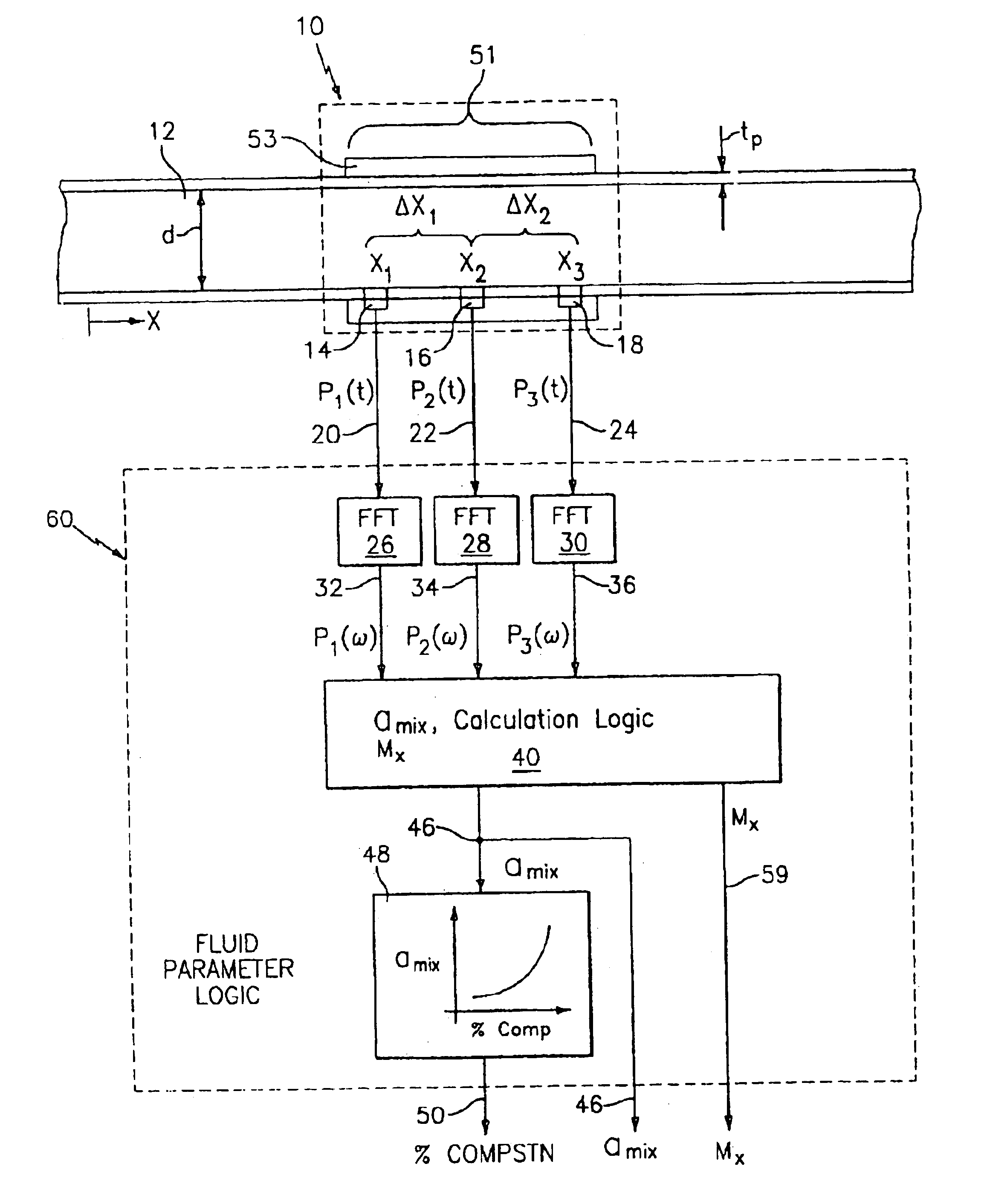
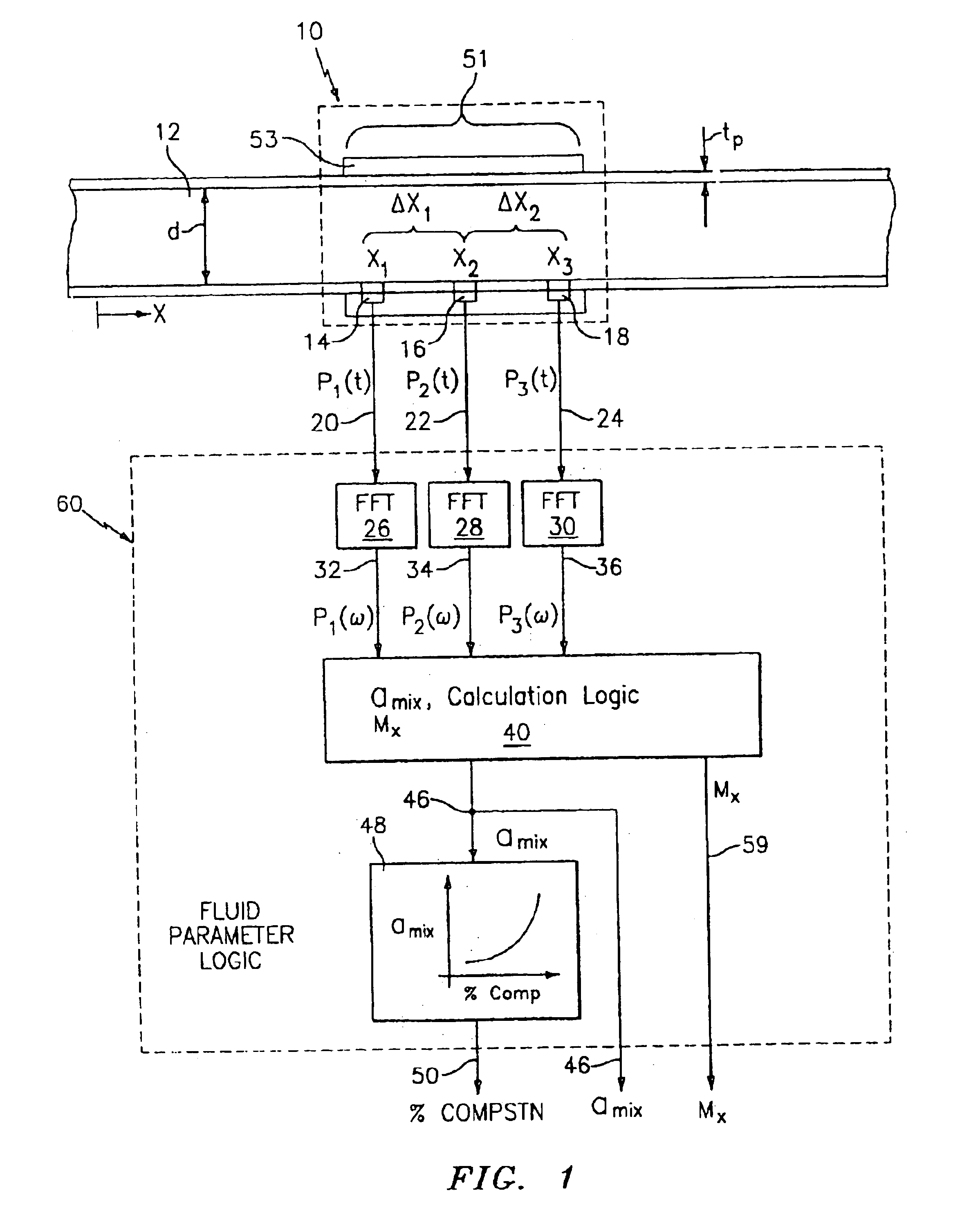
Referring to FIG. 1, a pipe (or conduit) 12 has three acoustic pressure sensors 14, 16, 18, located at three locations x1, x2, x3 along the pipe 12. The pressure may be measured through holes in the pipe 12 ported to external pressure sensors or by other techniques discussed hereinafter. The pressure sensors 14, 16, 18 provide pressure time-varying signals P1(t), P2(t), P3(t) on lines 20, 22, 24, to known Fast Fourier Transform (FFT) logics 26, 28, 30, respectively. The FFT logics 26, 28, 30 calculate the Fourier transform of the time-based input signals P1(t), P2(t), P3(t) and provide complex frequency domain (or frequency based) signals P1(ω), P2(ω), P3((ω) on lines 32, 34, 36 indicative of the frequency content of the input signals. Instead of FFTs, any other technique for obtaining the frequency domain characteristics of the signals P1(t), P2(t), P3(t), may be used. For example, the cross-spectral density and the power spectral density may be used to form frequency domain transf...


PUM

PropertyMeasurementUnit
phase fractionaaaaaaaaaa
lengthaaaaaaaaaa
pressureaaaaaaaaaa

Abstract

At least one parameter of at least one fluid in a pipe is measured using a spatial array of acoustic pressure sensors placed at predetermined axial locations along the pipe 12. The pressure sensors provide acoustic pressure signals, which are provided to a signal processing system that determines the speed of sound amix of the fluid (or mixture) in the pipe 12 using acoustic spatial array signal processing techniques. Numerous spatial array processing techniques may be employed to determine the speed of sound amix. The speed of sound amix is provided to another logic system that calculates the percent composition of the mixture, e.g., water fraction, or any other parameter of the mixture or fluid which is related to the sound speed amix. The signal processing system may also determine the Mach number Mx of the fluid. The acoustic pressure signals measured are lower frequency (and longer wavelength) signals than those used for ultrasonic flow meters, and thus are more tolerant to inhomogeneities in the flow. No external source is required and thus may operate using passive listening. The invention will work with arbitrary sensor spacing and with as few as two sensors if certain information is known about the acoustic properties of the system.

Description

TECHNICAL FIELDThis invention relates to fluid parameter measurement in pipes and more particularly to measuring the speed of sound and parameters related to the speed of sound in fluids in pipes using acoustic pressures.BACKGROUNDIt is known that the speed of sound, amix, of fluids in pipes may be used to determine various parameters of the fluid, such as is described in U.S. Pat. No. 4,080,837, entitled “Sonic Measurement of Flow Rate and Water Content of Oil-Water Streams,” to Alexander et al.; U.S. Pat. No. 5,115,670, entitled “Measurement of Fluid Properties of Two-Phase Fluids Using an Ultrasonic Meter,” to Shen; and U.S. Pat. No. 4,114,439, entitled “Apparatus for Ultrasonically Measuring Physical Parameters of Flowing Media,” to Fick. Measuring the speed of sound in the fluids in the prior art typically involved using a pair of acoustic transmitters / receivers (transceivers) which generate a sound signal and measure the time it takes for the sound signal to travel between the...

Claims


Application Information

Patent Timeline
Patent Type & Authority Patents(United States)
IPC IPC(8): G01N29/02G01N29/42G01N29/46G01N29/36G01N29/024G01N29/44G01F1/86G01F1/66
CPCG01H5/00G01N29/024G01N29/42G01N29/46G01N2291/0217G01N2291/106G01N2291/0224G01N2291/02836G01N2291/02845G01N2291/02872G01N2291/0222
Inventor GYSLING, DANIEL L.KERSEY, ALAN D.PADUANO, JAMES D.
Owner WEATHERFORD TECH HLDG LLC
Why Eureka
Try Eureka