Steel cord for the reinforcement of a rubber article and tire

Inactive Publication Date: 2005-03-08
BRIDGESTONE CORP
View PDF19 Cites 73 Cited by
  • Summary
  • Abstract
  • Description
  • Claims
  • Application Information

AI Technical Summary

Benefits of technology

It is therefore, an object of the invention to provide a steel cord capable of developing a satisfactory durability by avoiding the precedent breakage in a part

Problems solved by technology

A pneumatic tire as a typical example of the rubber articles, particularly a tire for construction vehicles is mounted onto a large-size dump truck or the like used in, for example, a large-scale civil engineering work site or an ore mining site, and subjected to severe operating conditions on rough road surfaces under a heavy load.
As the above tire for the construction vehicle is particularly run on an irregular land having a violent unevenness under a heavy load, a tread of the tire is subject to a large deformation and hence a large compression force is repeatedly applied thereto.
In case

Method used


Image

  • Steel cord for the reinforcement of a rubber article and tire
  • Steel cord for the reinforcement of a rubber article and tire
  • Steel cord for the reinforcement of a rubber article and tire

Examples


Example

EXAMPLE 1

With respect to steel cords having a construction as shown in Table 1, the filament occupying ratio and the ratio of developing the cord tenacity are investigated. Moreover, the filament occupying ratio is a ratio of total sectional area of all filaments constituting the strand to area of a circumcircle formed by filaments constituting the outermost sheath layer as previously mentioned, and the ratio of developing the cord tenacity is a ratio by percentage of load at break of the cord to sum of tensile strengths of straight filaments constituting the cord. The measured results are also shown in Table 1.

TABLE 1ConventionalConventionalExampleExampleComparativeExampleExampleExampleExampleExample1-11-2Example1-11-21-31-41-5Construction of cord7 × 12 + 17 × 27 + 17 × 31 + 17 × 11 + 17 × 24 + 17 × 24 + 111 + 6 × 12 + 124 + 6× 27 + 1(FIG. 1)(FIG. 4)(FIG. 5)(FIG. 5)(FIG. 2)(FIG. 3)Construction of core3 + 93 + 9 + 153 + 10 + 183 + 83 + 8 + 133 + 8 + 133 + 83 + 8 + 13strandConstructi...

Example

EXAMPLE 2

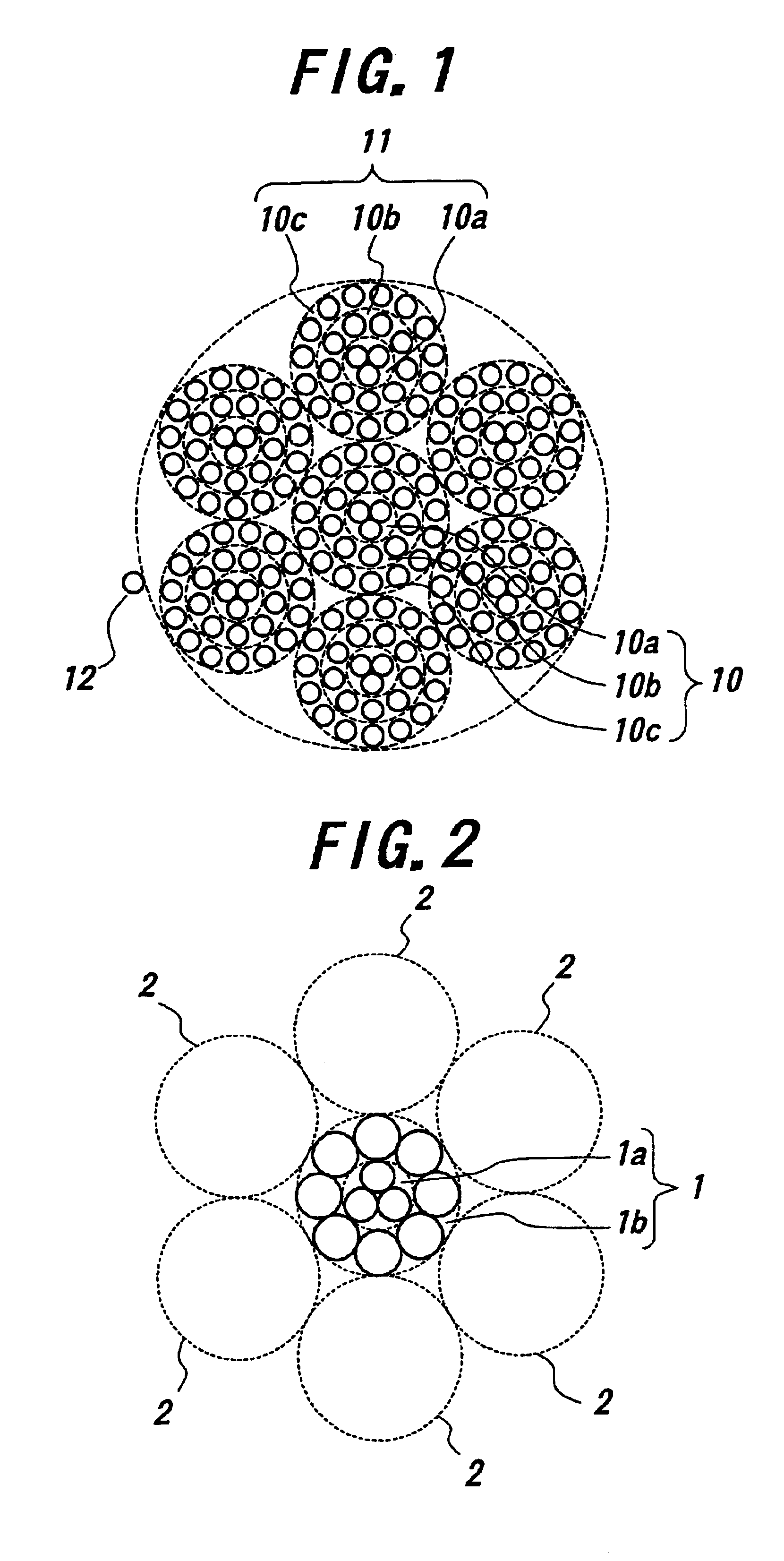
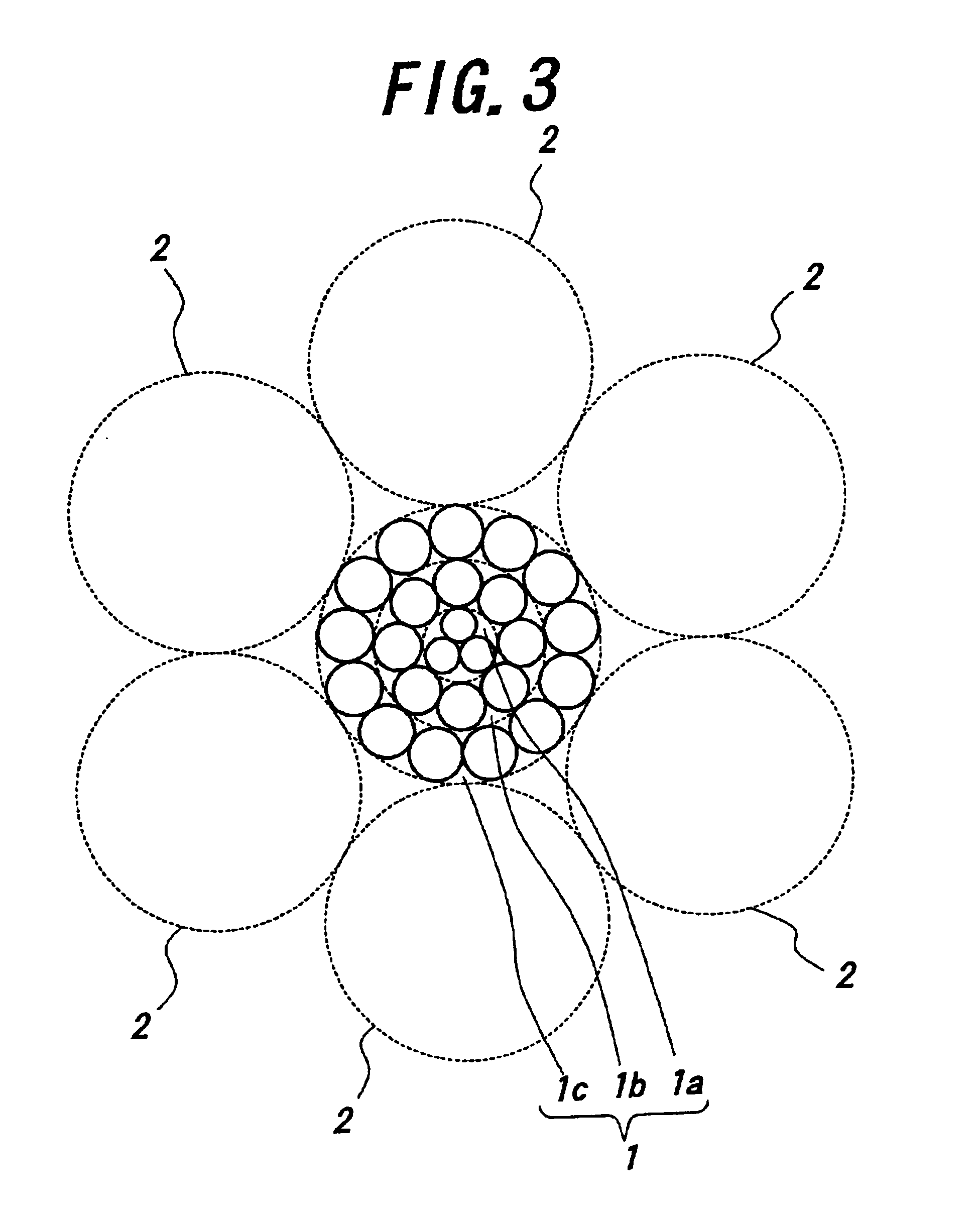
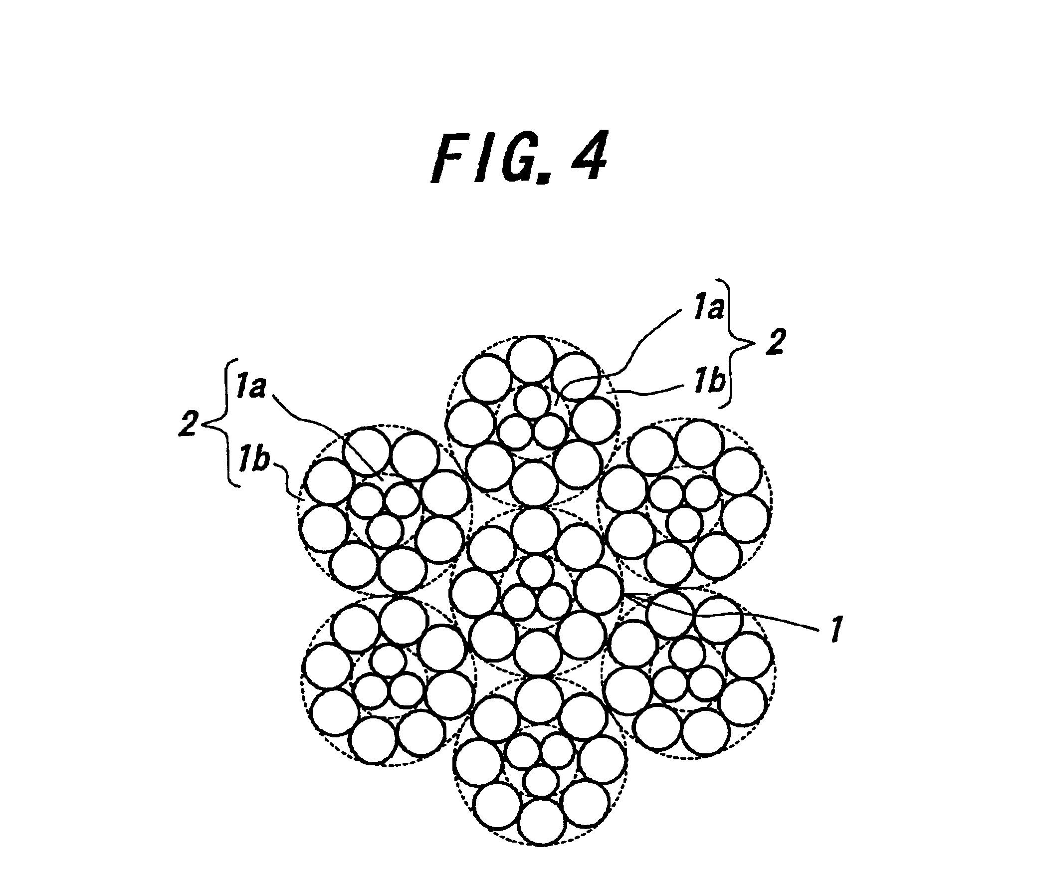
With respect the steel cords having a construction as shown in tables 2 and 3, the filament occupying ratio and the ratio of developing the cord tenacity are investigated. Moreover, the filament occupying ratio is a ratio of total sectional area of all filaments constituting the strand to area of a circumcircle formed by filaments constituting the outermost sheath layer as previously mentioned, and the ratio of developing the cord tenacity is a ratio by percentage of load at break of the cord to sum of tensile strengths of straight filaments constituting the cord. The measured results are also shown in Tables 2 and 3. Moreover, Tables 2 and 3 show a group of cords prepared under the same twisting angle in all cords every each Table.

TABLE 2ConventionalConventionalExample 21Example 22Example 21Example 22Construction of cord7 × 27 + 17 × 27 + 17 × 24 + 127 + 6 × 24 + 1(FIG. 1)(FIG. 1)(FIG. 6)(FIG. 8)Construction of core strand3 + 9 + 153 + 9 + 153 + 9 + 123 + 9 + 15Constructio...


PUM

PropertyMeasurementUnit
Diameteraaaaaaaaaa
Diameteraaaaaaaaaa
Distanceaaaaaaaaaa

Abstract

A steel cord having a strand construction formed by twisting a plurality of sheath strands each formed by twisting plural filaments around a core strand formed by twisting plural filaments is provided. At least one of the core strand and the sheath strands has a construction of twisting one or more sheath layers each made of plural filaments around a core made of one or plural filaments, and a diameter of a filament constituting an outermost sheath layer is made larger than that of a filament constituting at least one layer located inside thereof, whereby precedent breakage in a part of the filaments is avoided to improve the durability of the steel cord.

Description

TECHNICAL FIELDThis invention relates to steel cords used as a reinforcing member for rubber articles such as a tire, an industrial belt and the like, and particularly intends to improve a durability of the rubber article.BACKGROUND ARTA pneumatic tire as a typical example of the rubber articles, particularly a tire for construction vehicles is mounted onto a large-size dump truck or the like used in, for example, a large-scale civil engineering work site or an ore mining site, and subjected to severe operating conditions on rough road surfaces under a heavy load. This type of the tire is general to have a reinforcing structure that a carcass toroidally extending between a pair of bead cores is a skeleton and also a plurality of belt layers are arranged at an outside of the carcass in a radial direction.As the above tire for the construction vehicle is particularly run on an irregular land having a violent unevenness under a heavy load, a tread of the tire is subject to a large defo...

Claims


Application Information

Patent Timeline
IPC IPC(8): B60C9/00D07B1/06D07B1/00B60C9/02B60C9/20
CPCB60C9/0007B60C9/2006D07B1/0613B60C9/02Y10S57/902D07B1/0626D07B1/0633D07B2201/1068D07B2201/2006D07B2201/2023D07B2201/2037D07B2201/2051D07B2201/2061D07B2501/2046D07B2801/12D07B2801/24D07B2401/208D07B1/0606
Inventor MASUBUCHI, HIDEKIFUKUDA, YUKIMASA
Owner BRIDGESTONE CORP
Why Eureka
Try Eureka