Motor vehicle drive arrangement

a technology for motor vehicles and drive arrangements, applied in electric propulsion mounting, transportation and packaging, gearing, etc., can solve the problems of not being able to maintain transmission-oil pressure, no longer being able to dispense with the start/stop operation of internal combustion engines during the operation,

Inactive Publication Date: 2005-03-08
DAIMLER AG
View PDF20 Cites 98 Cited by
  • Summary
  • Abstract
  • Description
  • Claims
  • Application Information

AI Technical Summary

Benefits of technology

The invention has the advantage that the full operating-liquid pressure is already present in the drive system during the start of a motor vehicle or in fractions of seconds thereafter. A further advantage of the invention is that, to achieve the object, a pump already present even in series production vehicles with an automatic transmission can continue to be used and can be used at the same point as hitherto and is sufficient as the sole pump, in that the latter can, if required, be driven electrically, irrespective of the operating state of the locomotive drive engine.
is that, to achieve the object, a pump already present even in series production vehicles with an automatic transmission can continue to be used and can be used at the same point as hitherto and is sufficient as the sole pump, in that the latter can, if required, be driven electrically, irrespective of the operating state of the locomotive drive engine.
This means that only a single pump is required, which can be operated selectively by the locomotive drive engine (internal combustion engine or electric motor or other type of engine) or by an additional electrical machine which can be operated as an electric motor. This additional electrical machine may, if desired, be used as a generator for current generation, for example as a brake generator, at operating times when it is not required as an electric motor. Since the pump already present in series production vehicles can be used, it can, for example, continue to remain accommodated in a torque converter bell of an automatic transmission where it is already arranged even in known motor vehicles which do not have an additional electrical machine as an alternative drive for the oil pump. Furthermore, according to the invention, the external oil pump necessary hitherto in conjunction with start / stop operation or in the case of hybrid drive systems is not needed.
This means that, whenever the rotational speed of the transmission input shaft is too low in start / stop systems, the liquid pump (oil pump) can be operated by means of the electrical machine additionally integrated in the transmission case. This takes place, in the invention, via at least one free-wheel or, according to a preferred embodiment, via two free-wheels in the pump drive. As soon as the internal combustion engine or the transmission input shaft (which can be driveable by the internal combustion engine or by a hybrid system) rotates more rapidly than the additional electrical machine, the liquid pump can be operated by the transmission input shaft. When the transmission input shaft is at a standstill or is running at a low rotational speed, the electrical machine can, as an electric motor, drive the pump, without torque being transmitted to the transmission input shaft (and a converter or the locomotive drive transmission). The liquid-pressure supply of the automatic transmission is thus always ensured even when the rotational speed of the converter or of the transmission input shaft is not sufficiently high.
The invention is described below by means of preferred embodiments as examples, and with reference to the drawings.

Problems solved by technology

In view of increasing requirements for the reduction of consumption and emission, in the future, it will no longer be possible to dispense with a start / stop operation of the internal combustion engine during brief interruptions in the travel of the motor vehicle, in particular at traffic-light intersections.
Consequently, with the internal combustion engine switched off, the transmission-oil pressure (for shifting and lubrication of multiple-disc clutches or other clutches in the automatic transmission and / or of one or more shiftable clutches preceding the latter) cannot be maintained.
This presents problems during the start / stop operation of the internal combustion engine, since a rapid “drive-on” of the vehicle is not possible.
This additional external oil pump conventionally consists of a pump and of an electrical drive machine and, because of the large amount of space which it requires, can hardly be accommodated in present-day motor vehicles.
Efforts to integrate hybrid systems in the locomotive drive train and / or to replace the hydrodynamic torque converter of the automatic transmission by the hybrid system lead to the same set of problems which are that no transmission-oil pressure or insufficient transmission-oil pressure can be generated when the transmission input shaft, which may serve for driving the oil pump, is stationary or is running at only a low rotational speed.
The problem that there is not sufficient transmission oil and / or not a sufficient transmission-oil pressure or pressure for main clutches of the motor vehicle in order to start the motor vehicle quickly arises not only in the case of vehicle drives of an internal combustion engine, but also in the case of vehicle drives which have another locomotive drive engine instead of an internal combustion engine, for example an electric motor which, for example, is supplied with electrical energy by a fuel cell.

Method used


Image

  • Motor vehicle drive arrangement
  • Motor vehicle drive arrangement
  • Motor vehicle drive arrangement

Examples


Embodiment Construction

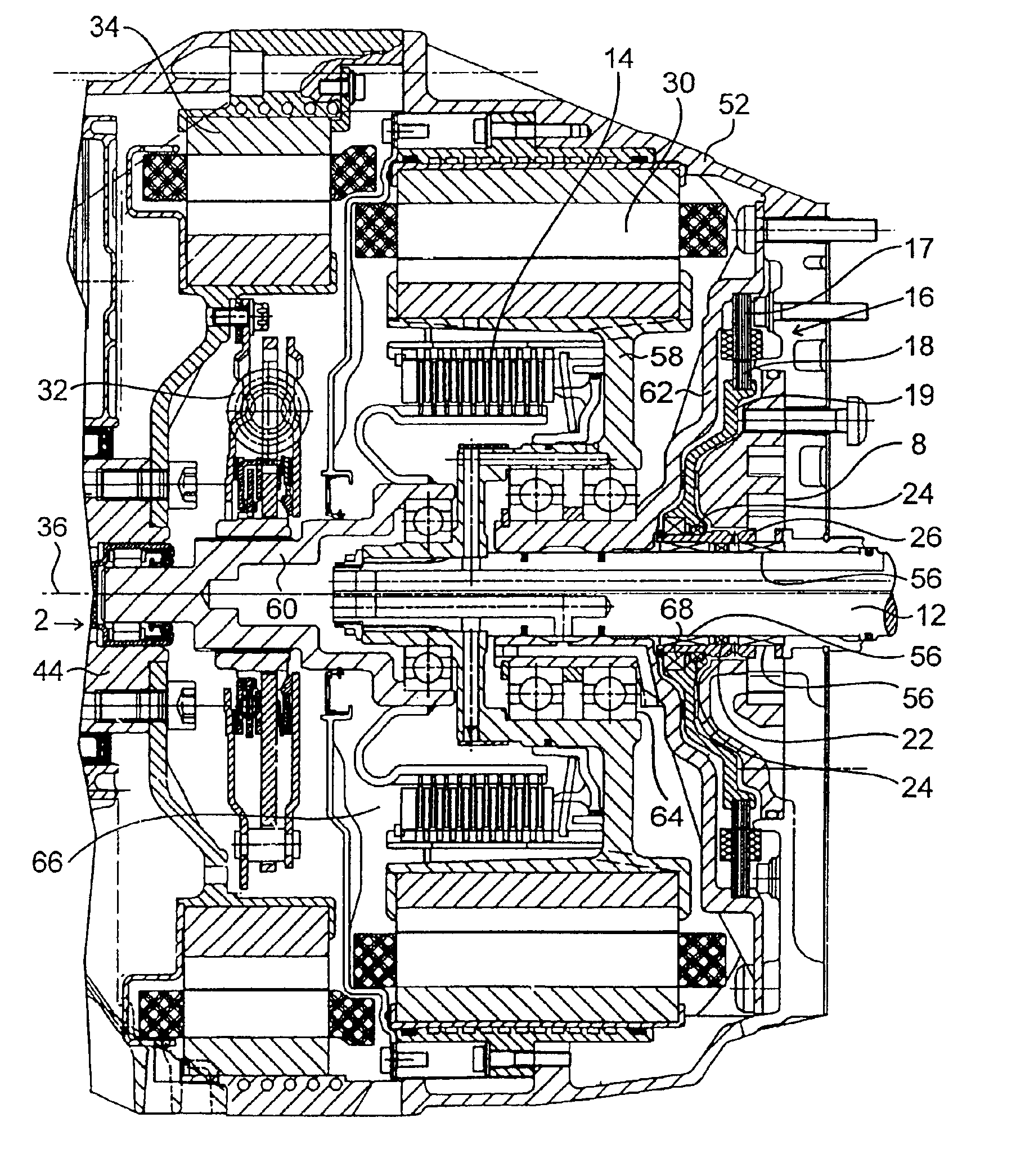
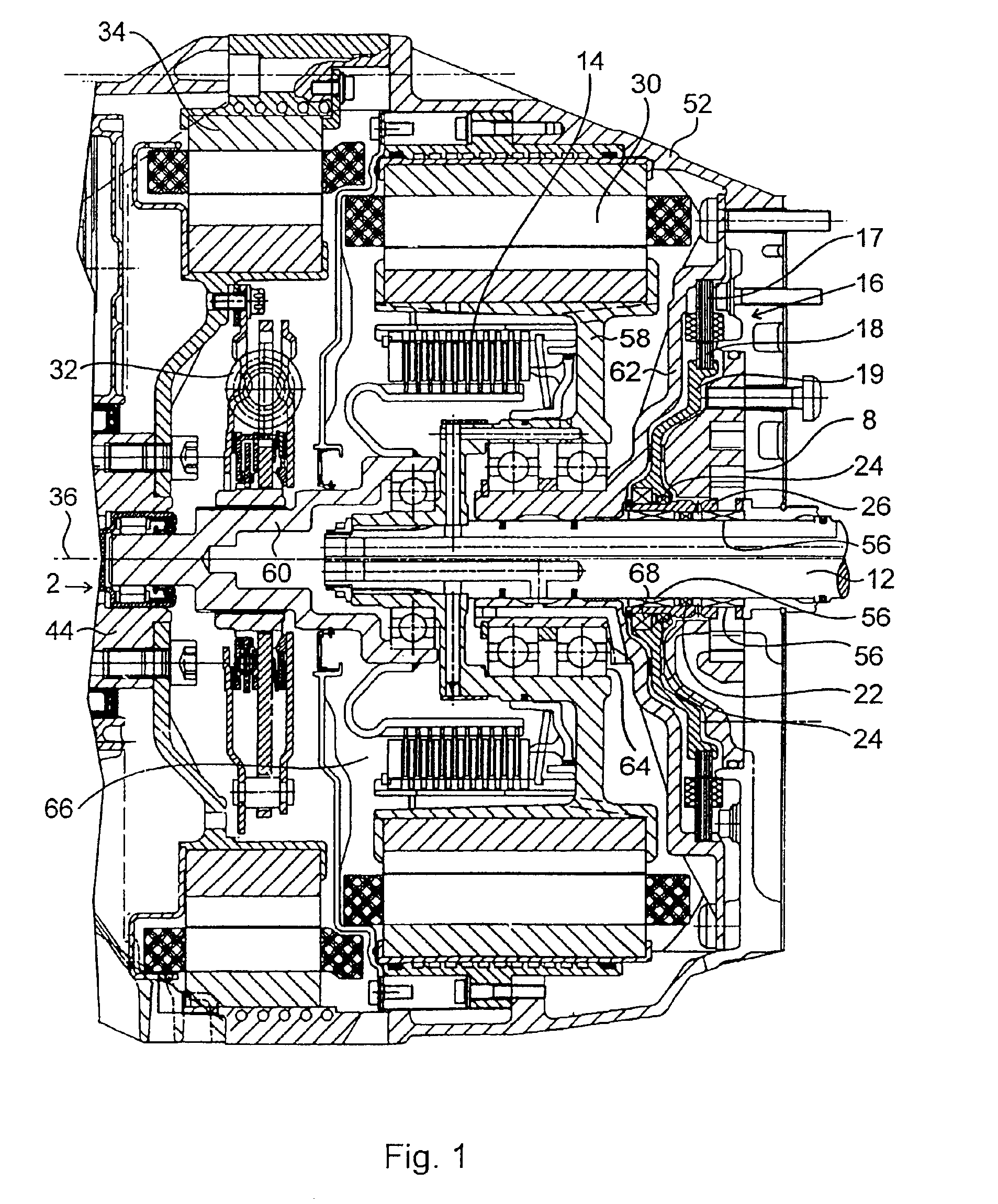
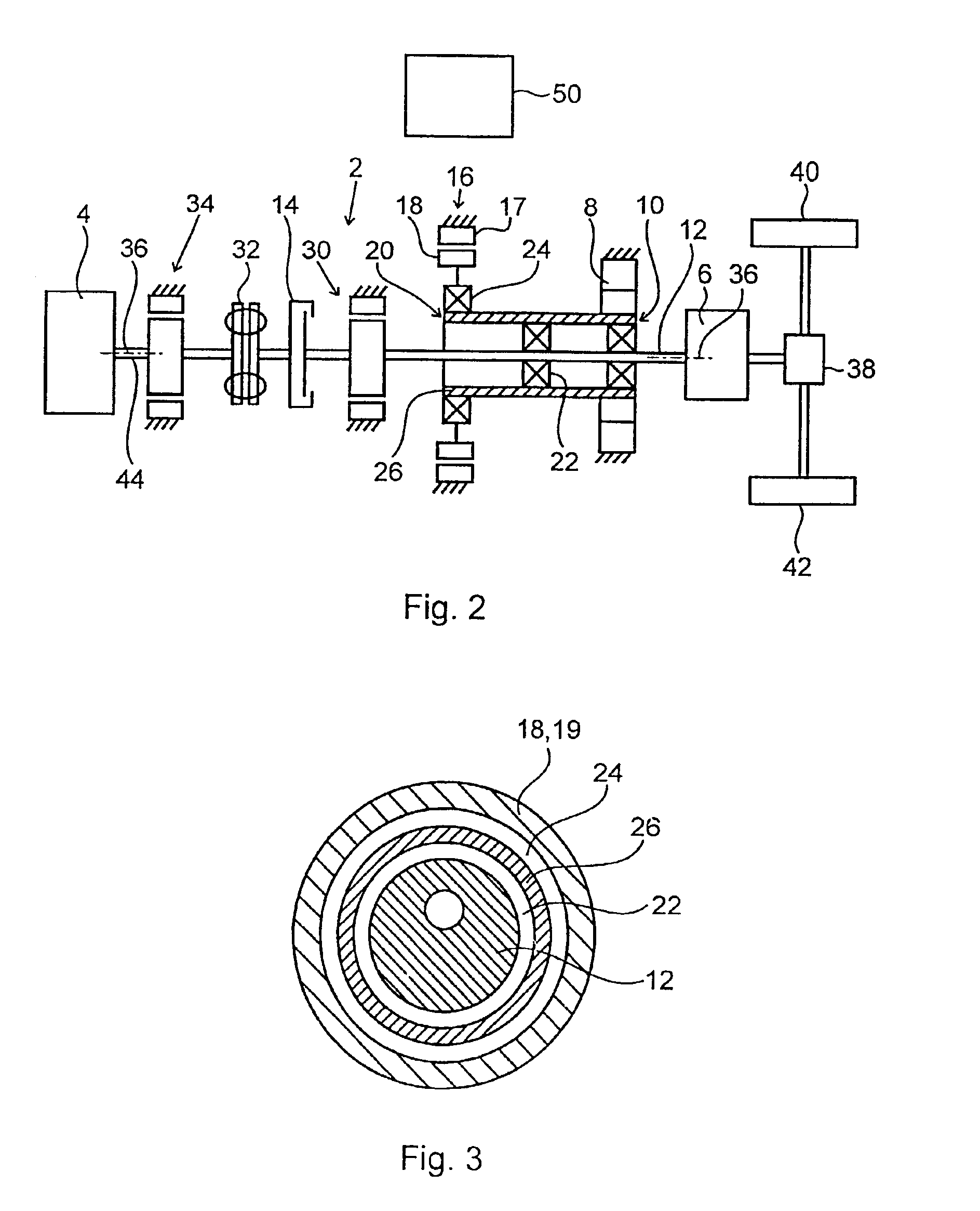
As is evident particularly from FIG. 2, the motor vehicle drive arrangement contains a locomotive drive train 2 for transmission of drive torque from a locomotive drive engine 4 to a locomotive drive transmission 6. Furthermore, a liquid pump 8 (oil pump) for supplying at least one drive part with operating liquid and a first pump drive connection 10 from a rotary part 12 of the locomotive drive train 2 to the liquid pump 8 are provided. In the embodiment shown, the rotary part 12 of the locomotive drive train 2 is the transmission input shaft of the locomotive drive transmission 6 which is preferably an automatic transmission with automatically shiftable gears. It can be used with or without a preceding torque converter. According to another embodiment, the locomotive drive transmission 6 could also be a manually shiftable transmission.

According to the drawings, the rotary part 12 is preferably the transmission input shaft to the locomotive drive transmission. It could, however, al...


PUM


Abstract

A motor vehicle drive arrangement has a locomotive drive train and at least one liquid pump capable of being driven by the latter. During a standstill in rotation or during very slow rotation of the locomotive drive train, the pump is capable of being driven by an electric motor instead of by the locomotive drive train. Beyond a defined minimum rotational speed of the locomotive drive train, the liquid pump is capable of being driven by the latter instead of by the electric motor. At least one free-wheel is provided for this purpose.

Description

MOTOR VEHICLE DRIVE ARRANGEMENTThis application claims the priority of German application 101 60 466.1, filed Dec. 8, 2001, the disclosure of which is expressly incorporated by reference herein.BACKGROUND AND SUMMARY OF THE INVENTIONThe present invention relates to a motor vehicle drive arrangement including a locomotive drive train for transmission of drive torque from a locomotive drive engine to a locomotive drive transmission, at least one liquid pump for supplying at least one drive part with operating liquid, and a first pump drive connection from a rotary part of the locomotive drive train to the liquid pump. The rotary part of the locomotive drive train is a drive shaft which is drive-connected or drive-connectable to the locomotive drive transmission. Such an arrangement also includes an electrical machine capable of being operated as an electric motor and having a rotor which is drive-connected or drive-connectable to the liquid pump by way of a second pump drive connectio...

Claims


Application Information

Patent Timeline
Patent Type & Authority Patents(United States)
IPC IPC(8): B60K6/04B60K6/00F16H61/00F16D45/00B60K6/383B60K6/40B60K6/405B60K6/442B60K6/547
CPCB60K6/40B60K6/405B60K6/442B60K6/547B60K25/02B60W10/06B60W10/08B60W10/30B60W20/00F16D45/00F16H57/043F16H57/0439F16H61/0025F16H61/0028B60K6/383B60K1/02Y10S903/919Y02T10/6234Y02T10/6286Y10S903/951Y10S903/913Y10S903/952B60K2006/268Y02T10/62
Inventor NOREIKAT, KARL-ERNSTOSTERTAG, TOBIASSAROCH, LARS
Owner DAIMLER AG
Why Eureka
Try Eureka