

Fan filter unit
A filter and fan technology, applied in the direction of machine/engine, ventilation system, mechanical equipment, etc., can solve the problem of inconsistent speed
- Summary
- Abstract
- Description
- Claims
- Application Information
AI Technical Summary
Problems solved by technology
Method used
Image

Examples
Embodiment approach 1
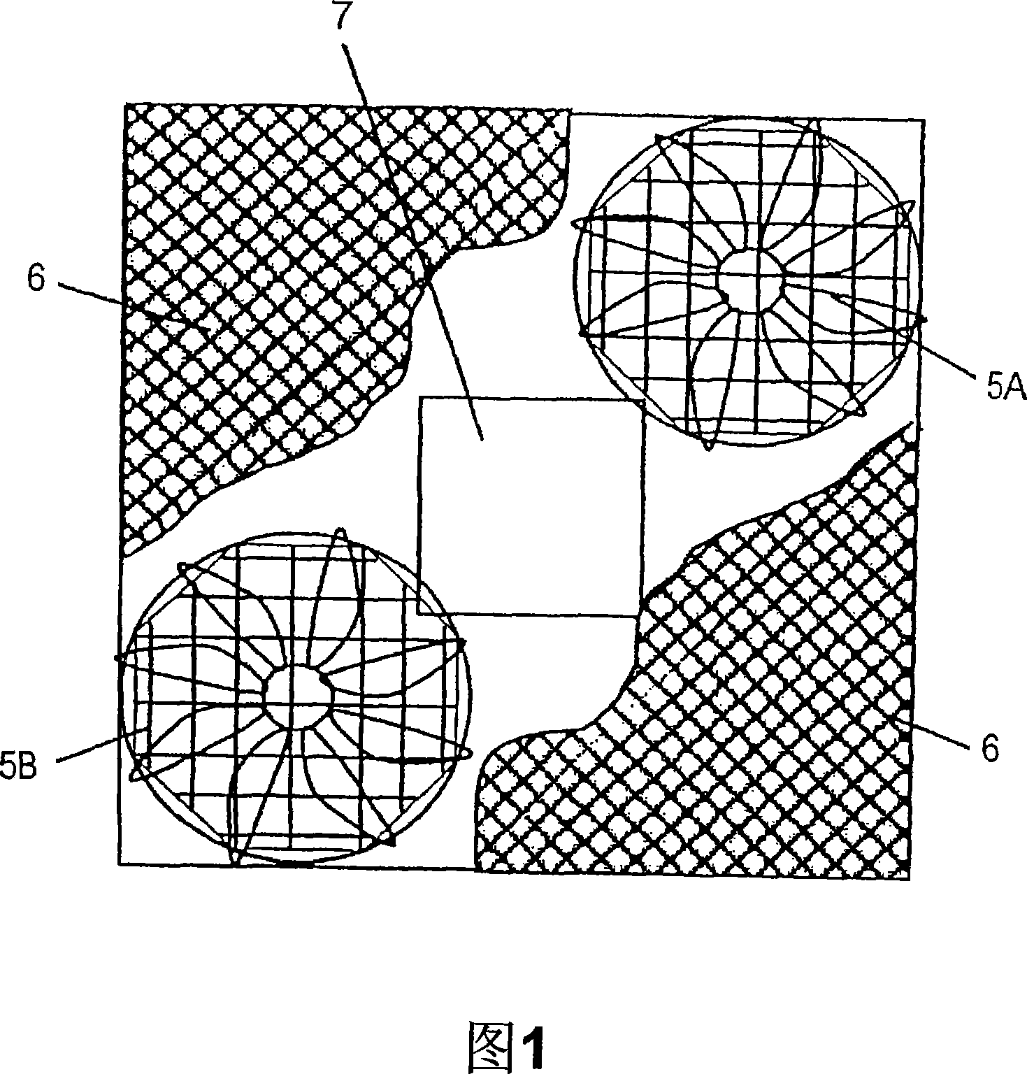
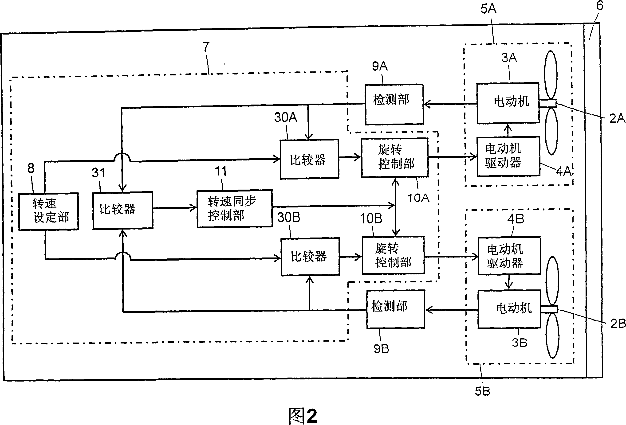
[0040] Fig. 1 shows a schematic structure of a fan filter unit according to Embodiment 1 of the present invention, and is a front view showing a state in which a part of the filter is cut away. Figure 2 is a block diagram of its circuit. This fan filter unit has a first fan motor 5A, a second fan motor 5B and a filter 6 . The fan motor 5A is composed of the first fan 2A, the first motor 3A and the first motor driver 4A, and the fan motor 5B is composed of the second fan 2B, the second motor 3B and the second motor driver 4B. The filter 6 serves to clean the air delivered by the fans 2A, 2B. The filter 6 is made of, for example, glass fibers, and captures micron-order fine particles with high efficiency. More specifically, the filter 6 traps fine particles of 0.3 μm with a collection efficiency of 99.97% or more. The filter 6 is arranged on the blowing side or the suction side of the fans 2A, 2B.
[0041] This fan filter unit has a body control part (hereinafter referred to...
Embodiment approach 2
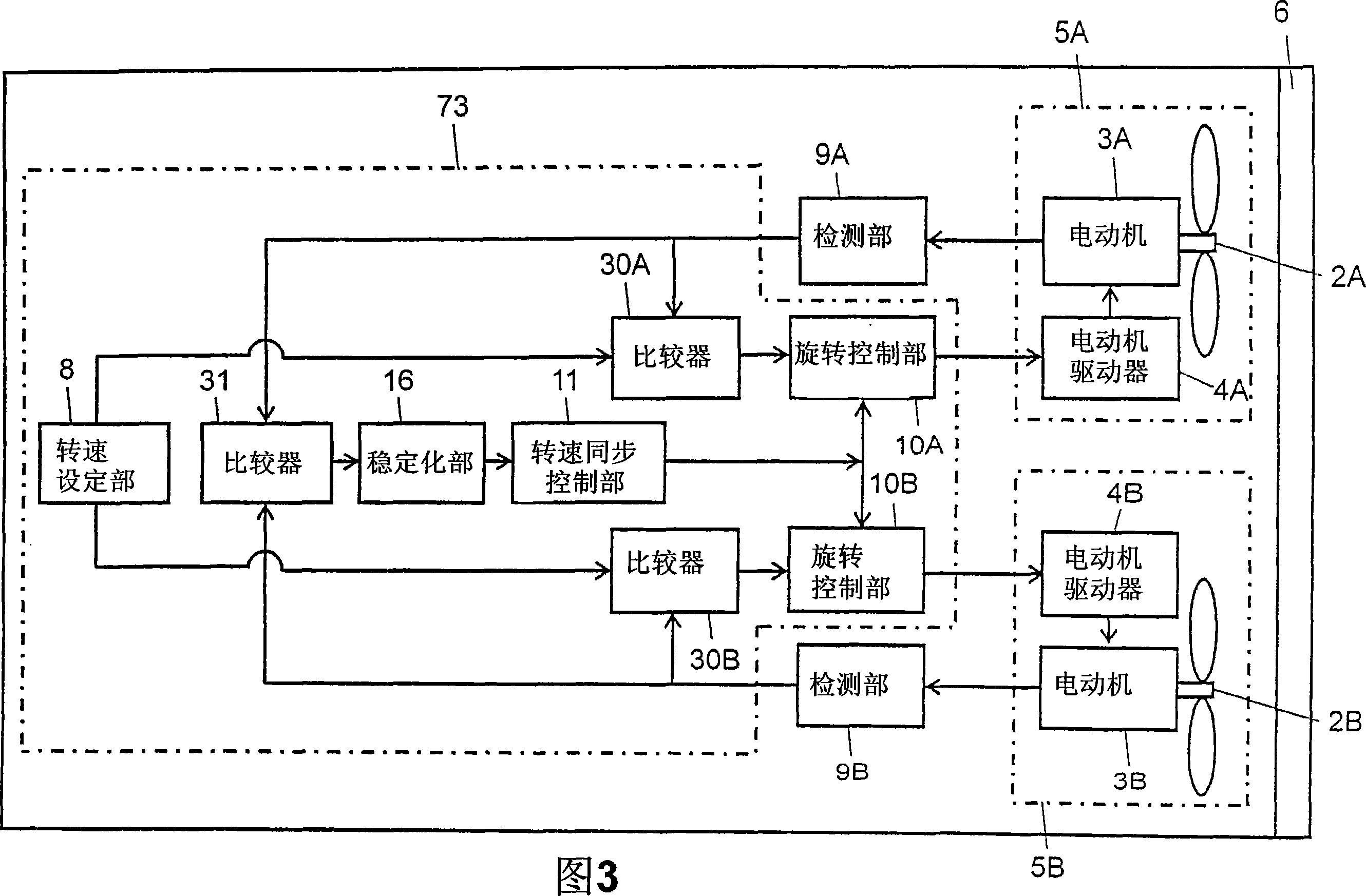
[0052] Fig. 3 is a circuit block diagram of the fan filter unit according to Embodiment 2 of the present invention. The structure of this embodiment differs from the structure of Embodiment 1 in that a stabilization unit 16 is provided between a comparator 31 and a rotational speed synchronous control unit (hereinafter referred to as a control unit) 11 in a main body control unit 73 . Other configurations are the same as those of Embodiment 1.
[0053] The stabilizing unit 16 disables the function of the control unit 11 until the preparatory operation for a predetermined time has elapsed. Stabilizing unit 16 prevents control unit 11 from functioning in the time zone when the detected rotational speed of fan motors 5A, 5B is unstable when fan motors 5A, 5B are just starting to operate or when the rotational speed fluctuates instantaneously. The stabilization unit 16 is also constituted by a microcomputer or the like.
[0054] That is to say, for example, in the case where the...
Embodiment approach 3
[0058] Fig. 4 is a circuit block diagram of the fan filter unit according to Embodiment 3 of the present invention. The configuration of this embodiment differs from that of Embodiment 1 in that a retry unit 19 is provided in the main body control unit 74 . Other configurations are the same as those of Embodiment 1. The retry unit 19 is also constituted by a microcomputer or the like.
[0059] The retry unit 19 has a retry function, and when the rotational speed synchronous control unit (hereinafter referred to as the control unit) 11 continuously performs the rotational speed synchronous control for a predetermined time, it performs trial control so that the rotational speed of the fans 2A, 2B is equal to the rotational speed setting. The set speed of the part 8 is the same.
[0060] When an important process is performed in a clean room with a fan filter unit, stopping the fan motors 5A, 5B may significantly reduce the productivity of the process. Therefore, it is desirab...
PUM
 Abstract
Description
Claims
Application Information