container for microwave oven
A technology for microwave ovens and containers, which is applied in containers, food heating containers, applications, etc. It can solve the problems of container body deformation, membrane blockage, and steam beeping, etc., and achieve the effect of suppressing beeping and preventing water droplets from staying
- Summary
- Abstract
- Description
- Claims
- Application Information
AI Technical Summary
Problems solved by technology
Method used
Image
Examples
Embodiment approach 1
[0040] (The overall structure of the container for microwave oven)
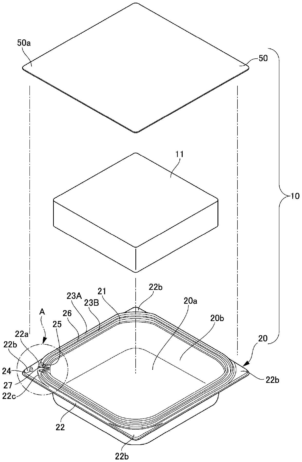
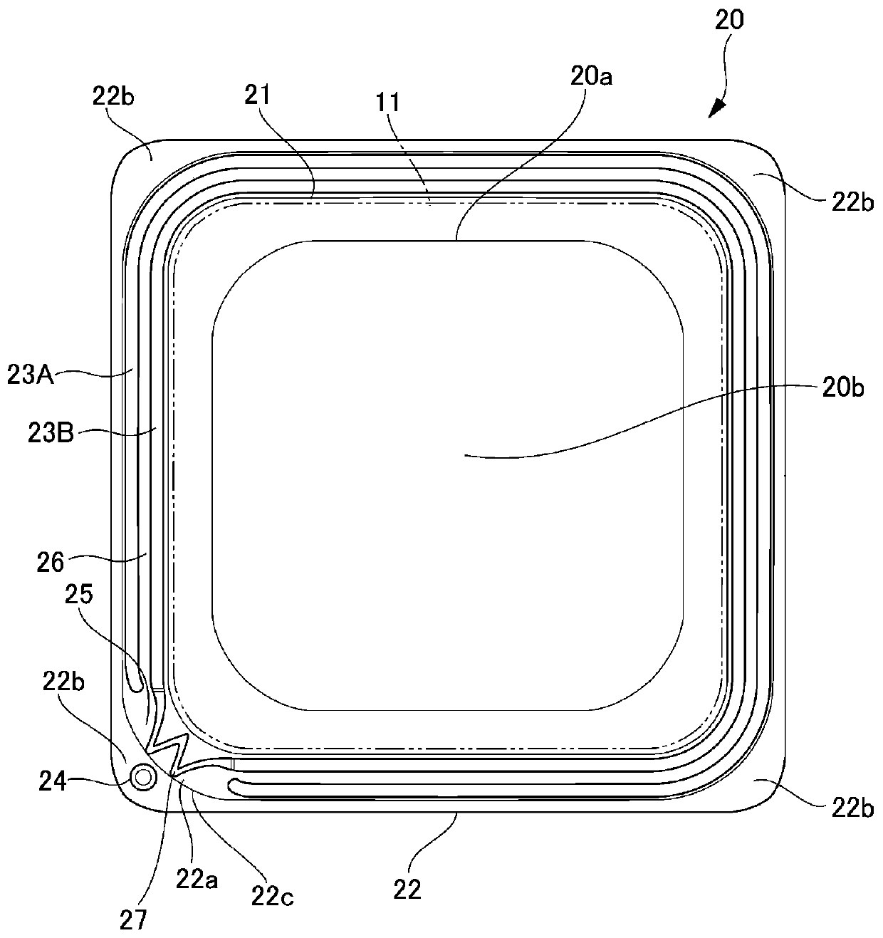
[0041] First, based on figure 1 The overall configuration of the container for a microwave oven according to Embodiment 1 will be described. picture figure 1 As shown, the container 10 for a microwave oven mainly includes a container main body 20 having an opening 21 and filling the contents 11 from the opening 21 , and a film-shaped lid member 50 closing the opening 21 . Both the container main body 20 and the lid member 50 are formed of a resin material. The contents 11 stored in the container main body 20 are various foods and the like, as long as they can be heated in a microwave oven, the type is arbitrary.
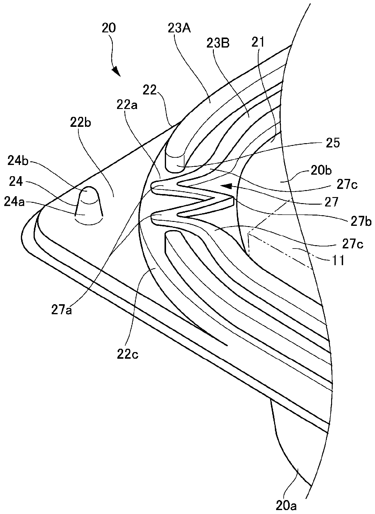
[0042] Further, container 10 for microwave oven includes flange portion 22 , second heat-welded portion 23A formed on the upper surface of flange portion 22 and heat-sealed to lid member 50 , and first heat-sealed portion 23B on its outer peripheral side. Furthermore, the container 10 for a micr...
Embodiment approach 2
[0070] Below, based on Figure 8 Embodiment 2 of the present invention will be described. In Embodiment 2, in the W-shaped portion 27 (easily peelable portion) in Embodiment 1, the inner central tip portion 27b is made lower than the inner two root portions 27c, 27c, and the height difference is h2. That is, the central two side portions 27d, 27d connecting the outer two tip portions 27a, 27a and the inner central tip portion 27b are formed more gentle than the root side portions 27e, 27e connecting the outer two tip portions 27a, 27a and the inner two root portions 27c, 27c. The inclination angle θ2. With this configuration, when the lid member 50 is thermally welded to the flange portion 22 of the container body 20, the central two sides 27d, 27d and the root two sides 27e, 27e sandwiching the outer two sharp ends 27a, 27a can be heated. Since the strength of welding is more different, the stress on the vapor pressure of the outer tip portions 27a, 27a is more concentrated...
Embodiment approach 3
[0073] Below, based on Figure 9 A container body according to Embodiment 3 of the present invention will be described. In Embodiment 3, the planar shape of the storage portion 20b is a substantially oval shape with rounded corners. picture Figure 9 As shown, the container main body 70 has the storage part 20b and the opening 21 whose planar shape is substantially rectangular. The flange portion 22 extending from the opening 21 is provided with a ridge-shaped second heat-sealing portion 23A and a ridge-shaped first heat-sealing portion 23B. Furthermore, the first heat-sealing portion 23B has a W-shaped portion 71 , and the W-shaped portion 71 is formed in a W-shape so as to close outward at a position corresponding to the steam discharge portion 25 in plan view. The W-shaped portion 71 has two outer two tip portions 71a, 71a facing outward, one inner central tip portion 71b facing inward, and two inner root portions 71c, 71c connected to the first thermally welded portion ...
PUM
 Abstract
Description
Claims
Application Information
 - R&D
- Intellectual Property
- Life Sciences
- Materials
- Tech Scout
- Unparalleled Data Quality
- Higher Quality Content
- 60% Fewer Hallucinations
Browse by: Latest US Patents, China's latest patents, Technical Efficacy Thesaurus, Application Domain, Technology Topic, Popular Technical Reports.
© 2025 PatSnap. All rights reserved.Legal|Privacy policy|Modern Slavery Act Transparency Statement|Sitemap|About US| Contact US: help@patsnap.com


