Eureka AIR delivers breakthrough ideas for toughest innovation challenges, trusted by R&D personnel around the world.

Auger with forward angled leading edge

a leading edge and auger technology, applied in grain processing, grain husking, transportation and packaging, etc., can solve the problems of reducing the mixing ability and processing speed of the mixer, requiring more horsepower, and requiring more horsepower, so as to reduce the wrap-around and build-up problems, reduce energy consumption, and increase the productivity of the agricultural mixer

Inactive Publication Date: 2005-03-08
KUHN KNIGHT
View PDF19 Cites 16 Cited by
  • Summary
  • Abstract
  • Description
  • Claims
  • Application Information

AI Technical Summary

Benefits of technology

Accordingly, it is, therefore, desirable to have an improved design for augers that can reduce these wrap-around and build-up problems in order to reduce the energy consumption and to increase the productivity of agricultural mixers and other similar devices.
Thus, one of the objectives of the present invention is to provide a vertical mixer auger with a forward leading edge, which overcomes the problems associated with prior art devices and makes a considerable contribution to the art of mixing feed materials. Depending on the embodiment of the present invention, other advantages include, for example:(a) providing a leading edge that creates a wedge effect while in rotary motion, allowing it to more easily move through feed materials;(b) providing a leading edge that reduces the horsepower required to mix feed materials;(c) providing a leading edge that tends to cut or slice material with a longer slanted edge rather than pushing material with a shorter straight edge;(d) providing a leading edge that improves the sweeping action at the floor of the mixer; and(e) providing a leading edge that is more durable and efficient in use.

Problems solved by technology

A disadvantage of the straight leading edge design is that it tends to push or plow materials rather than scooping the material on top of itself.
This resulting plowing action requires higher horsepower, and limits the mixing ability and processing speed of the mixer.

Method used


Image

  • Auger with forward angled leading edge
  • Auger with forward angled leading edge
  • Auger with forward angled leading edge

Examples


Embodiment Construction

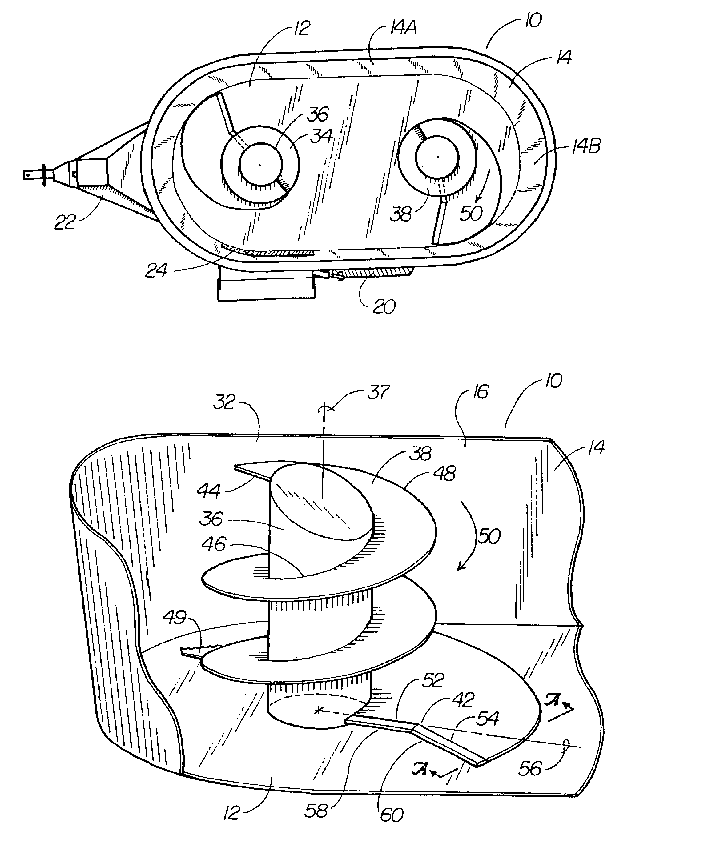
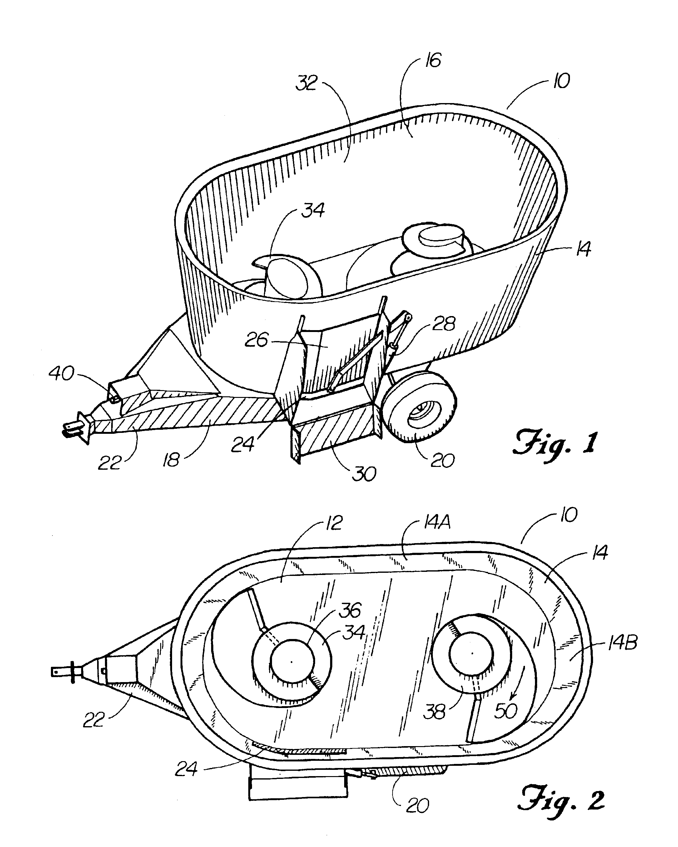
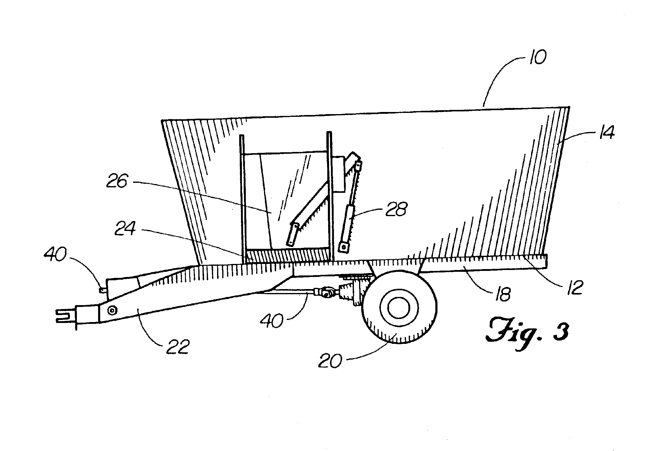
With reference to the drawings, a vertical feed mixer is generally designated by the reference number 10. As illustrated in FIGS. 1-3, the mixer includes a floor 12, a sidewall 14, and an open upper end 16. The mixer is mounted upon a frame 18, including wheels 20. A tongue 22 extending from the frame 18 is adapted to be hitched to a tractor or other prime mover. The sidewall 14 includes a discharge opening 24 with a discharge door 26 movable between open and closed positions by a hydraulic cylinder 28. A discharge chute 30 extends outwardly adjacent to the discharge opening 24.

The floor 12 and the sidewall 14 define a mixing chamber 32. An auger 34 is rotatably mounted within the mixing chamber 32, and includes a vertically disposed core 36. As illustrated, the mixing chamber 32 may also include two or more augers 34. The core 36 and the auger 34 rotate around an axis of rotation 37, as shown in FIG. 4. A helical flighting 38 is secured to and disposed coaxially with the core 36. A...


PUM


Abstract

An auger for vertical mixers includes a forward angled leading edge. The leading edge includes an inner portion, which may or may not be aligned with a radial line extending from the axis of rotation of the auger. The leading edge also includes an outer portion adjacent to the inner portion, which is angled forward of the radial line and extends forward of the inner portion.

Description

BACKGROUND OF THE INVENTIONField of the InventionThis invention relates generally to vertical augers, and in one embodiment this invention pertains to vertical augers used in agricultural mixers.DISCUSSION OF THE BACKGROUNDAgricultural mixers are used for mixing feed materials such as hay, silage and other nutrients including animal feed supplements and grains. These feed materials are then discharged and fed to various livestock such as cattle and dairy cows. Sometimes the mixing of such feed materials includes depositing a whole round or square bale of hay into the mixer. The mixer then cuts and processes the bale into the desired consistency before and during the mixing of the other feed nutrients.In known mixers, there are many different configurations including horizontal augers, reel-type arrangements, and vertical augers. In the vertical auger type mixers, the auger designs are often very similar. The auger generally consists of a center core on a vertical axis, with helical ...

Claims


Application Information

Patent Timeline
Patent Type & Authority Patents(United States)
IPC IPC(8): A01K5/00B01F13/00B01F13/10B01F7/24B01F7/00
CPCA01K5/004B01F13/105B01F13/1025B01F7/241B01F7/00208B01F13/0035B01F27/091B01F27/922B01F33/502B01F33/82B01F33/833
Inventor KNIGHT, WILLIAM S.
Owner KUHN KNIGHT
Why Eureka
Eureka Blog
Learn More