Stator vane span attachment for a gas turbine

a technology for gas turbines and stator vane spans, which is applied in the direction of stators, machines/engines, liquid fuel engines, etc., can solve the problems of affecting the fit used for attachment, affecting the mechanical strength of stator vane spans and their supports, and causing undesired noise, etc., to achieve the effect of increasing the restraining

Inactive Publication Date: 2005-03-08
ROLLS ROYCE DEUT LTD & CO KG
View PDF5 Cites 7 Cited by
  • Summary
  • Abstract
  • Description
  • Claims
  • Application Information

AI Technical Summary

Benefits of technology

In order to increase the restraining effect, it can be particularly advantageous if the radius of the casing in the area of the stator vane spans is smaller than the radius of the respective stator vane segment. This provides that the free end areas of the stator vane spans abut onto the casing and can be restrained accordingly.

Problems solved by technology

During operation of the stator vane spans in a compressor, high mechanical loads and temperature changes are encountered which can affect the fits used for attachment.
Vibrations can in this case occur, giving rise to the development of undesired noise and impairing the mechanical strength of the stator vane spans and their supports.

Method used


Image

  • Stator vane span attachment for a gas turbine
  • Stator vane span attachment for a gas turbine
  • Stator vane span attachment for a gas turbine

Examples


Embodiment Construction

This detailed description should be read in conjunction with the summary above, which is incorporated by reference in this section.

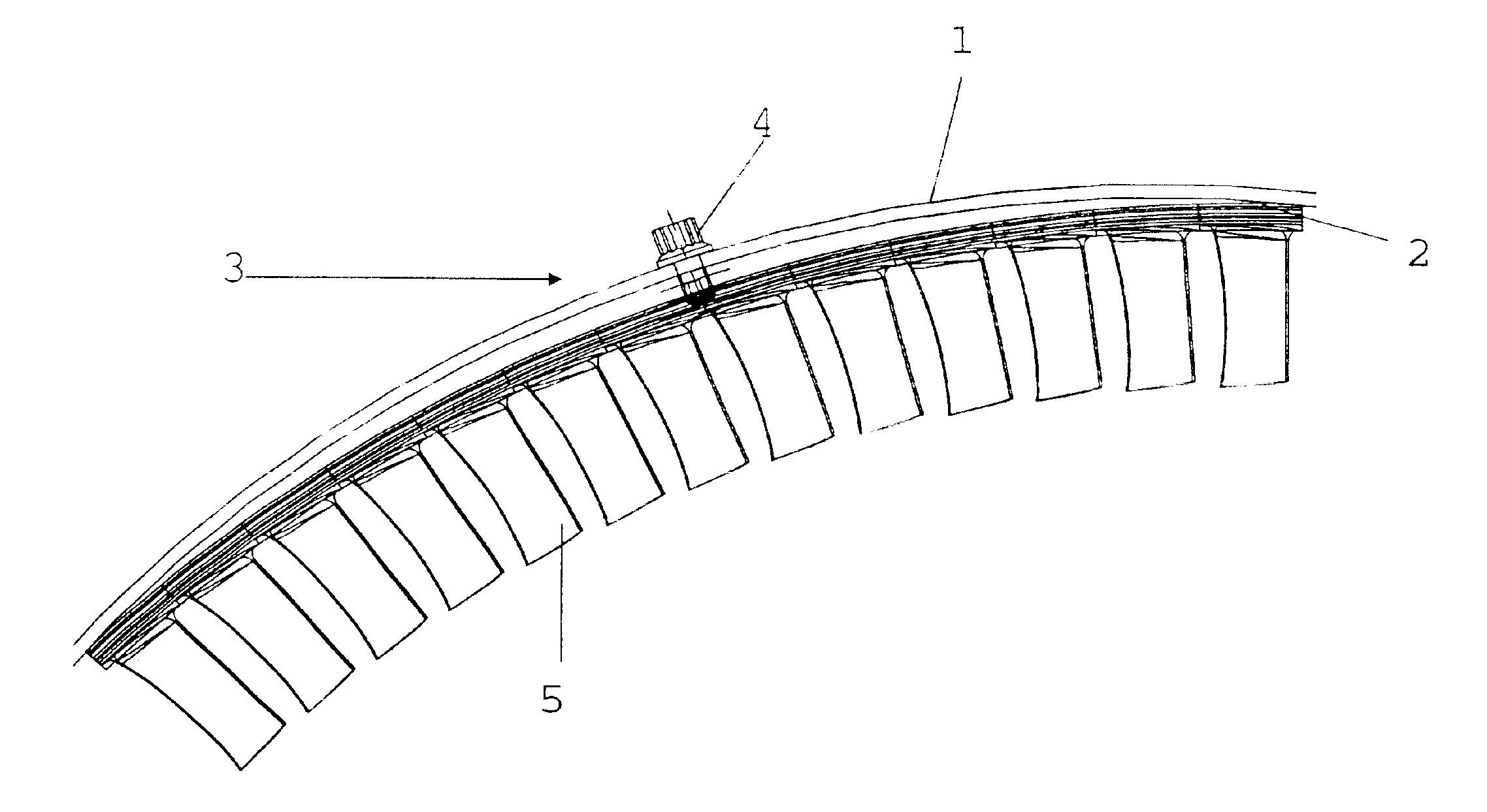
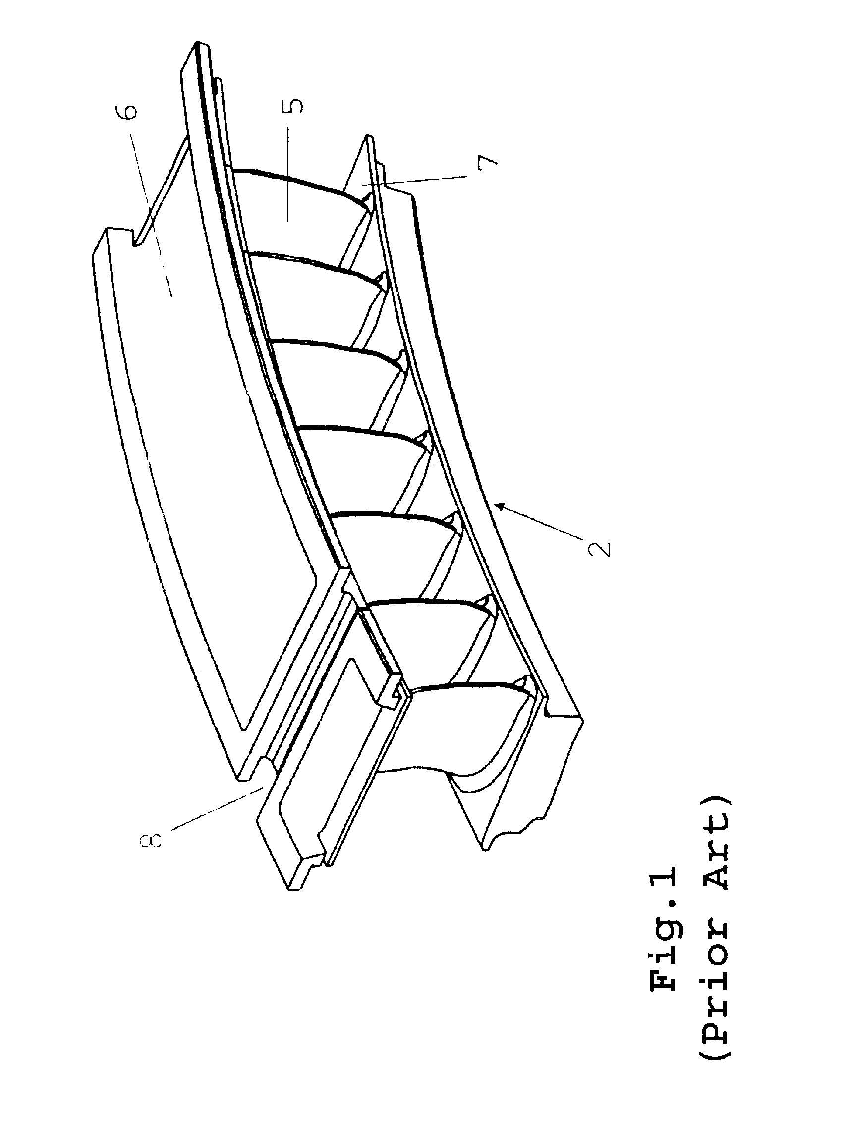
FIG. 1 shows, in perspective representation, a stator vane span, as it is known per se from the state of the art. The span comprises several stator vanes 5 which connect to a segmental outer support 6 and, optionally, to a segmental inner support 7. The outer support 6 and the inner support 7 can possess lateral legs or tangs or grooves, as applicable, to enable their attachment to a casing 1 (see FIG. 3) or to an inner shroud. These designs are known from the state of the art to which reference is herewith made. Rotation of the stator vane spans 2 in the casing can be avoided by so-called vane stops. For this purpose, the stator vane span shown in FIG. 1 features, for example, a groove 8.

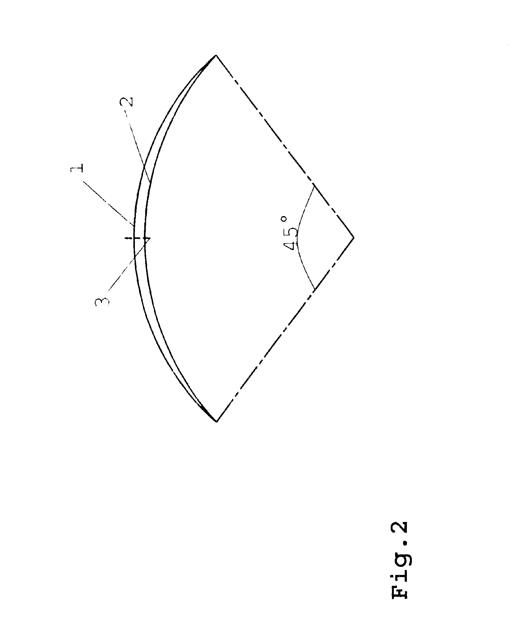
FIG. 2 shows, in schematic side view, the principle of function of the present invention prior to restraining. The outer circular arc represents a casing 1, while the i...


PUM


Abstract

A stator vane span attachment for a gas turbine having a casing 1 in which several stator vane spans 2 are located, wherein means 3 are provided for restraining the stator vane spans 2 against the casing 1.

Description

This application claims priority to German Patent Application DE10214569.5 filed Apr. 2, 2002, the entirety of which is incorporated by reference herein.BACKGROUND OF THE INVENTIONThis invention relates to a stator vane span attachment for a gas turbine featuring a casing on which several stator vane spans are located.Stator vanes of gas turbines are usually designed in the form of segments which are inserted in or fixed to a casing. Designs of the said type are shown in Specification U.S. Pat. No. 6,296,443 B1 by way of example.The individual vane spans inserted in or attached to a casing must be supported in such a manner that they are retained in the axial direction of the aero gas turbine and in the circumferential direction of the casing. For this purpose, the vane spans possess, for example, legs or grooves which make the applicable positive fit with the casing, as mentioned in the above US Specification. During operation of the stator vane spans in a compressor, high mechanic...

Claims


Application Information

Patent Timeline
Patent Type & Authority Patents(United States)
IPC IPC(8): F01D25/24F01D9/04F01D5/26F01D5/12F01D5/22
CPCF01D5/225F01D5/26F01D25/246F01D9/041F05D2230/64F05B2260/301
Inventor SEYDEL, CHRISTIANGOLOWIN, ANDREJ
Owner ROLLS ROYCE DEUT LTD & CO KG
Why Eureka
Try Eureka