Blast fan

a technology of a blast fan and a fan body is applied in the field of blast fans, which can solve the problems of not being able to blow a large amount of air, not being able to ensure a high flow rate, and increasing so as to reduce the noise generated by the fan, increase the flow rate of the fan, and achieve high air flow resistance

Inactive Publication Date: 2005-03-08
LG ELECTRONICS INC
View PDF5 Cites 7 Cited by
  • Summary
  • Abstract
  • Description
  • Claims
  • Application Information

AI Technical Summary

Benefits of technology

Therefore, the present invention has been made in view of the above problems, and it is an object of the present invention to provide a blast fan comprising a plurality of turbo blades, each integrally installed at an optimal position of a rotary blade, thereby achieving an increase in the flow rate of the fan and a reduction in noise generated from the fan, even in the case that the blast fan is mounted in a flow channel exhibiting a relatively high air flow resistance.

Problems solved by technology

These problems of the conventional axial flow fan 10 occur in other electric units including air-conditioners and microwave ovens as well as refrigerators.
Also, since the motor 12 has to be rotated at a high speed, the level of noise generated from the fan is increased.
Although a turbo fan, adapted to forcibly propel air, is applied to solve a high air flow resistance problem as stated above, it is still not sufficient to ensure a high flow rate.
Where the conventional blast fan is a kind of high static pressure and low flow rate type turbo fan, which is advantageously used under the high air flow resistance condition, it still fails to blow a large amount of air.

Method used


Image

  • Blast fan
  • Blast fan
  • Blast fan

Examples


Embodiment Construction

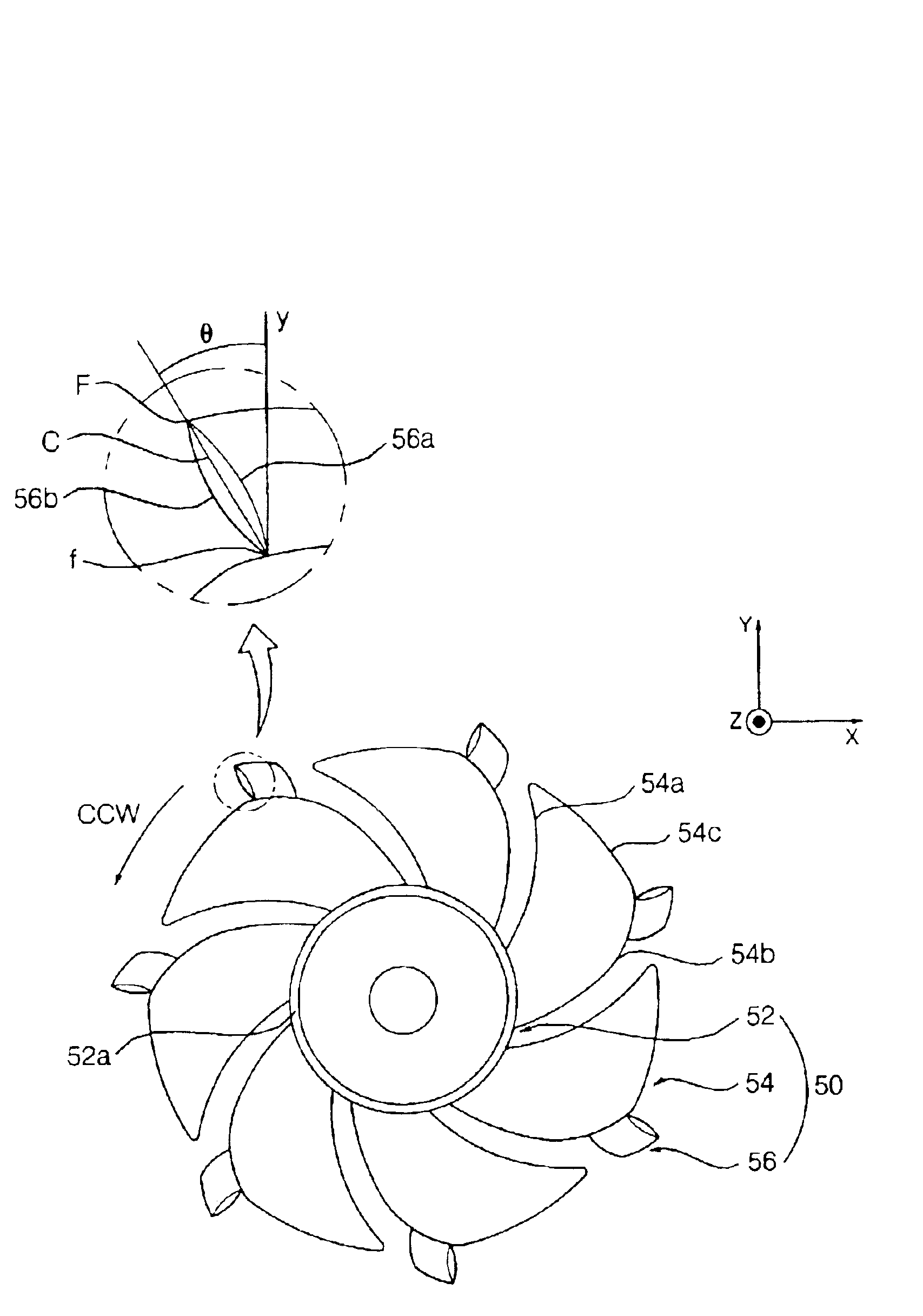
FIGS. 4 and 5 are a front view and a side view, respectively, showing the construction of a blast fan (CCW) in accordance with the present invention, and FIGS. 6 and 7 are a front view and a side view, respectively, showing the construction of the blast fan (CW) of the present invention.

The blast fan in accordance with the present invention is of axial flow type as shown in FIGS. 4 to 7. The axial flow fan 50 comprises a cylindrical hub 52 coupled to a rotating shaft of a motor (not shown) and having a horizontally extending outer peripheral surface 52a configured so that an inlet end thereof adapted to suck air has the same diameter as an outlet end thereof adapted to discharge the sucked air. The axial flow fan 50 further comprises a plurality of rotary blades 54 equally spaced and arranged around the outer peripheral surface 52a of the hub 52, and a plurality of turbo blades 56 integrally coupled with the rotary blades 54, respectively.

The hub 52 has a rotating shaft mount 52b ar...


PUM


Abstract

Disclosed is a blast fan for blowing air in a centrifugal direction thereof. The blast fan comprises a hub coupled to a rotating shaft of a motor, and a plurality of blades equally spaced and arranged around the outer peripheral surface of the hub. More particularly, the blast fan, of axial flow type or diagonal flow type, is configured so that turbo blades are integrally coupled to respective tips or trailing edges of the rotary blades. By achieving an optimal installation angle of the turbo blade, it is possible to achieve an increase in the flow rate and to reduce the level of noise generated.

Description

BACKGROUND OF THE INVENTION1. Field of the InventionThe present invention relates to a blast fan for blowing air in a centrifugal direction thereof, and more particularly to a blast fan having a plurality of turbo blades, each integrally installed to the tip or trailing edge of a rotary blade, for achieving an increase in the flow rate and a significant reduction in noise generated.2. Description of the Related ArtIn general, a blast fan is mounted to home electronics including refrigerators, air conditioners, microwave ovens and so on, and adapted to blow air while being rotated by a motor.FIG. 1 is a front view showing the construction of a conventional axial flow fan, FIG. 2 is a side view of the conventional axial flow fan, and FIG. 3 is a sectional view showing the construction of a refrigerator equipped with the conventional axial flow fan.The conventional axial flow fan, as shown in FIGS. 1 and 2, comprises a hub 2 coupled to a rotating shaft of a motor (not shown) and adapte...

Claims


Application Information

Patent Timeline
Patent Type & Authority Patents(United States)
IPC IPC(8): F04D29/38F04D29/28
CPCF04D29/384F25D2317/0681F04D29/28
Inventor JUNG, YOUNG GYUKIM, CHANG JOON
Owner LG ELECTRONICS INC
Why Eureka
Try Eureka