
Intravenous infusion needle with soft body

Inactive Publication Date: 2005-03-08
LUTHER NEEDLESAFE PRODS
View PDF35 Cites 17 Cited by
  • Summary
  • Abstract
  • Description
  • Claims
  • Application Information

AI Technical Summary

Benefits of technology

The present invention provides a catheter comprising a flexible tube with a sharpened needle tip permanently secured to a distal end of the catheter to facilitate insertion of the catheter into a patient's anatomical passageway. The sharpened needle tip secured to the catheter remains within the patient's blood vessel during treatment. As a result, the invention does not require that a separate sharpened needle be inserted with the catheter and then removed immediately after the catheter is properly positioned.
Another feature of this invention is that it provides a catheter with increased flexibility to minimize trauma to the interior of an anatomical passageway such as a blood vessel, which increases the time period during which the catheter remains viable within the patient, and also increases the length of catheter which can be maintained within the anatomical passageway. The flexibility of the tube allows the needle tip to be flow directed towards the center of the vessel thereby minimizing trauma to the vessel and increasing the time period during which the catheter remains viable.
An additional advantage of the preferred embodiment of this invention is that it provides a catheter tip formed of a material which minimizes the clotting of blood which may back up into the catheter.
A further feature of the preferred catheter assembly apparatus and method is that insertion of the catheter into a blood vessel or the like does not require a separate sharpened inserter to be used with the catheter. The catheter assembly comprises a catheter and a safety inserter. The safety inserter may be removably engaged within the catheter. Preferably, the inserter comprises a base portion and a distal end portion. The proximal end of the safety inserter is sized to accommodate a hydrophilic filter plug and / or a luer tip of a syringe. The distal end portion is sized to fit within the sharpened needle tip. The base portion is sized to fit within the flexible tube and to abut an annular shoulder formed by the proximate edge of the needle tip. Preferably, this inserter has a blunt distal end since the sharpened needle tip secured to the distal end of a flexible tube enables insertion of the catheter into the patient's anatomical passageway such as a blood vessel.
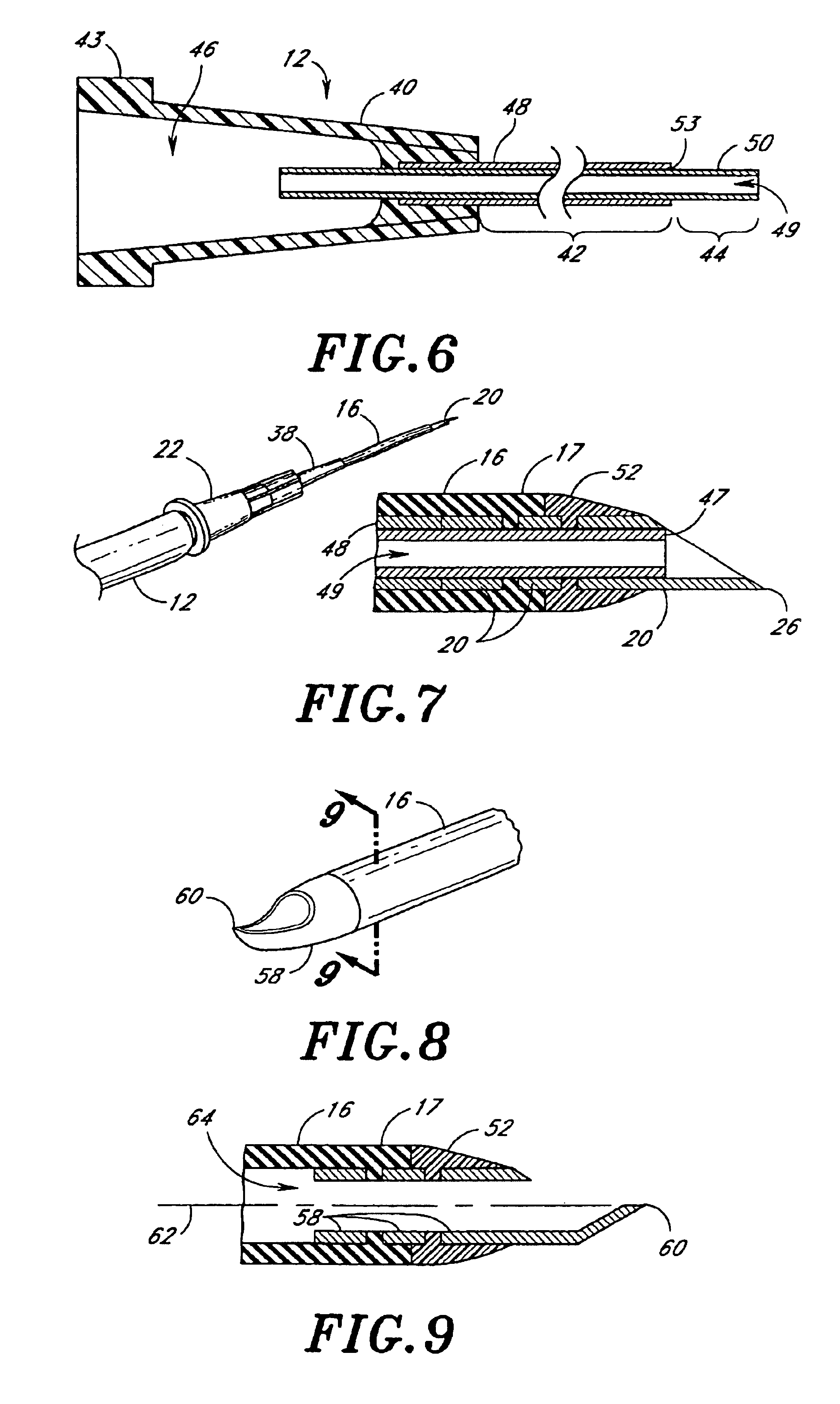
In accordance with a further aspect, the invention provides a needle tip and method of forming the same wherein the point of the needle tip is substantially aligned with a central axis of the lumen defined by the needle tip or cannula from which it was derived. The improved needle tip minimizes the risk of injury to walls of an anatomical passageway.

Problems solved by technology

A common problem associated with many over-the-needle catheters is that they tend to travel axially away from the tip of the needle and thus collapse during the insertion procedure.
Such stiffness traumatizes the walls of the anatomical passageway and typically requires removal of the catheter from the passageway or vessel in two days or less.
A significant disadvantage of both the prior art through-the-needle and over-the-needle systems is that a sharpened needle must be removed once the catheter has been inserted into the patient.
Removal of the sharpened needle undesirably exposes both the patient and the medical practitioner to accidental contact with the needle, a continuing problem in view of the highly contagious and / or fatal nature of such diseases as AIDS and Hepatitis A. Removal of the sharpened needle with the catheter in place also presents the problem of damage to the catheter itself.
However, current devices and methods still require some action by the medical practitioner to remove and dispose of a sharpened needle immediately after inserting the catheter.
The timing of this procedure presents drawbacks.
In addition to the above-described drawbacks associated with present catheters, catheters have also exhibited a limited useful lifetime or viability.
Thus, a catheter must be replaced numerous times in even a short hospital stay by a patient which increases the risks of accidental sticks and contamination.
The frequent replacement of catheters during the course of a patient's treatment also increases medical costs, in terms of both time and materials.
Such pressure may lead to damage to the inner walls of the patient's vein or even internal bleeding.
Although catheters are generally flexible, they have not heretofore been flexible enough to alleviate the problem associated with a catheter pressing against the inside of a patient's anatomical passageway.
Another problem associated with catheters relates to undesirable clotting of blood sometimes associated with certain materials of construction.
Depending upon the material of construction of the catheter, blood may form clots when it is drawn up into the catheter.
For example, when an instrument is removed from the fluid communication line connected to the catheter, it may result in a small decrease in pressure within the catheter thereby causing fluid to back up into the catheter from the patient's vascular system.
This can lead to various problems.
Because the tip of the catheter remains in contact with the blood when the catheter is disposed within a blood vessel, the material of construction of the inner portion of the catheter tip often plays a significant role in the degree of undesirable clotting.
While a needle formed in such a manner is highly effective for insertion, it can sometimes pass entirely through an anatomical passageway such as a blood vessel or can damage the opposing wall of the passageway during the insertion process.
Moreover, when the needle tip is to remain within the passageway for an extended period during treatment, such conventional needle tips may increase the possibility of trauma to the inside surface of the passageway depending upon the particular application.

Method used


Image

  • Intravenous infusion needle with soft body
  • Intravenous infusion needle with soft body
  • Intravenous infusion needle with soft body

Examples


Embodiment Construction

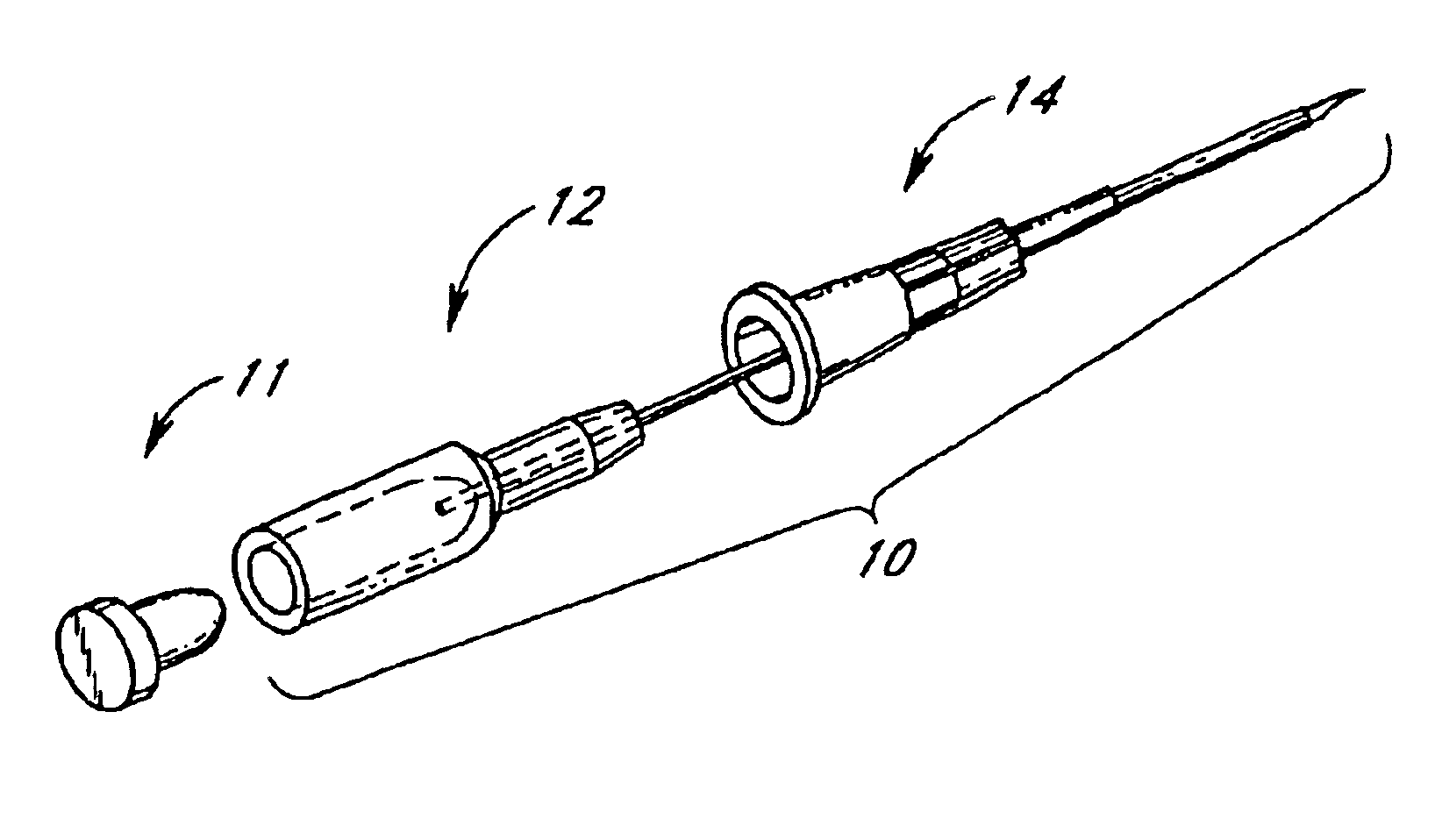
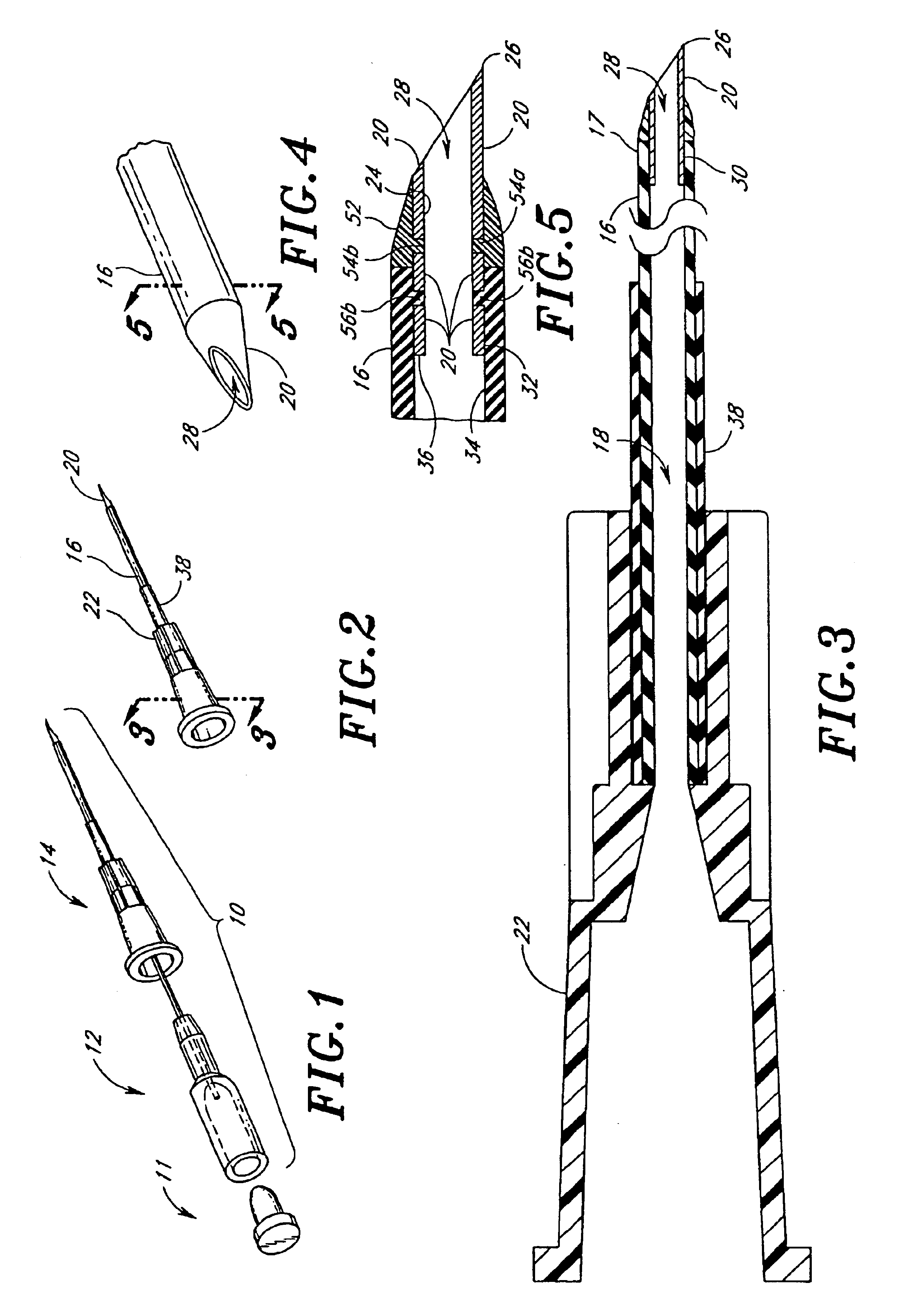
FIG. 1 depicts the improved catheter assembly 10 of the present invention. The catheter assembly 10 comprises a safety inserter 12 and a catheter 14.

Referring to FIGS. 2 and 3, the catheter 14 comprises a flexible tube 16 defining a lumen 18 therethrough. A sharpened needle tip 20 is secured to a distal end of the flexible tube 16. A hub 22 is formed at a proximal end of the catheter 14. The hub 22 facilitates connection of the catheter 14 with an administration line (not shown) to provide for the communication of fluids through the catheter 14, as will be easily understood by those skilled in the art.

The flexible tube 16 advantageously is preferably formed of a soft thermoplastic material. Preferably, the flexible tube 16 is formed of a material having a hardness value between 50 and 90 Shor A, more preferably between 65 and 85 Shor A, and most preferably approximately 70 Shor A. In a preferred embodiment, the flexible tube 16 is formed of polyurethane. A suitable polyurethane is s...


PUM


Abstract

Disclosed is a catheter having a flexible tube and a sharpened needle secured to the catheter at its distal end. The catheter does not require a separate sharpened instrument to enable insertion into an anatomical passageway. The sharpened needle of the catheter remains disposed within an anatomical passageway during treatment. Also disclosed is a catheter assembly comprising the catheter and a safety inserter. The safety inserter has a blunt end and facilitates the insertion of the catheter by providing a mechanism to urge the sharpened needle of the catheter into an anatomical passageway. Also disclosed is an improved needle tip which minimizes trauma to an anatomical passageway. Also disclosed are methods of using and forming the catheter, catheter assembly and needle tip.

Description

BACKGROUND OF THE INVENTIONThe present invention relates to an improved catheter, and more particularly to an improved catheter which provides an increased viable lifetime and also minimizes potential trauma to the patient and the possibility of accidental needle contact with the medical practitioner.Catheters are used for introducing fluids into an anatomical passageway of a patient undergoing treatment. Typically, a catheter is inserted into the anatomical passageway, such as a blood vessel. The catheter is then connected to an administration line from which fluids are introduced into the patient's vascular system through the catheter. Alternatively, catheters may be placed directly into tissue of a patient, such as a muscle or organ so that a fluid medication may be administered directly to a specific site asystemically as is well understood by those of skill in the art.There are various methods of inserting a catheter into an anatomical passageway. These methods typically involv...

Claims


Application Information

Patent Timeline
IPC IPC(8): A61M25/06A61M25/00A61B17/34
CPCA61M25/0643A61M25/06A61M25/0068A61B17/3496
Inventor LUTHER, RONALD B.
Owner LUTHER NEEDLESAFE PRODS
Learn More