Biodegradable fixation element

a technology of fixation element and biodegradable material, which is applied in the field of biodegradable fixation element, can solve the problems of insufficient bone growth or insufficient fixation, and the inability to fix new transplants, and achieve the effects of prolonging the mechanical anchoring of the transplant, simple fabrication, and retaining the stability of the elemen

Inactive Publication Date: 2005-03-08
KARL STORZ GMBH & CO KG
View PDF14 Cites 319 Cited by
  • Summary
  • Abstract
  • Description
  • Claims
  • Application Information

AI Technical Summary

Benefits of technology

The holes instead of only pores allow a fast bone growth in a remarkable extend into the interior of the fixation element. The entire fixation body surface is covered with bone growth. When the material is reabsorbed, one obtains a bone network structure which is sufficiently stable. If a revision is necessary after unsuccessful anchoring of the transplant or after a rupture of the transplant, the network structure presents no problem in the case of a revision. Sufficient bone material is available, even if the biodegradable material is not yet completely absorbed, to not only maintain a very stable and durable anchoring of the transplant, but also to provide sufficient bone material for setting further borings.
Most of the perforations are formed to be holes completely passing through a wall of a hollow body. This feature has the advantage that the perforations are simple to fabricate, while the stability of the element is still retained.
Further, the perforations are formed between the anchoring elements. That feature has the-considerable advantage that the anchoring elements can be configured to be very stable or massive to be able to exert or to receive the corresponding anchoring forces and not be weakened by the perforations. This design allows a growth of bone material via the holes into the interior simultaneously to the biodegradation of the body. The fact that the holes are not present within the anchoring elements but only between them, maintains the mechanical strength of the body and consequently the anchoring of the transplant for a long time period, during that time period a biodegradation already takes place, in particular in the area of the holes i.e. between the anchoring elements. This prolongs the mechanical anchoring of the transplant by the fixation element and simultaneously an enhanced anchoring by the grown bone material.
In a further embodiment of the present invention, the element comprises a channel completely passing through the element. The feature has the advantage that the channel having a corresponding contour can act to receive a tool for screwing in the fixation element, when configured as an interference screw. The bone material on the other hand can also grow into the open ends of the channel into the interior. In addition, bone material can be placed in the channel, for example bone slurry or bone pieces, which for example have been removed from the pelvic crest region. This bone material then grows together with the bone cells entering through the perforations to form a rigid bone composite. It is also possible to deposit anticyto-statics or antibiotics to avoid infections. Growth factors (hormones, etc.) can also be provided in the interior space. These can also be deposited on the surface of the element during fabrication or be embedded in the degradable material.

Problems solved by technology

If the biological degradation does not take place parallel with the bone growth, instable conditions can arise in that the bone growth is not sufficient or is not sufficiently fixed, while hollow spaces have already arisen due degradation.
However, if sufficient bone material is not present, these borings cannot be properly made and correspondingly the new transplant cannot be fixed.

Method used


Image

  • Biodegradable fixation element
  • Biodegradable fixation element
  • Biodegradable fixation element

Examples


Embodiment Construction

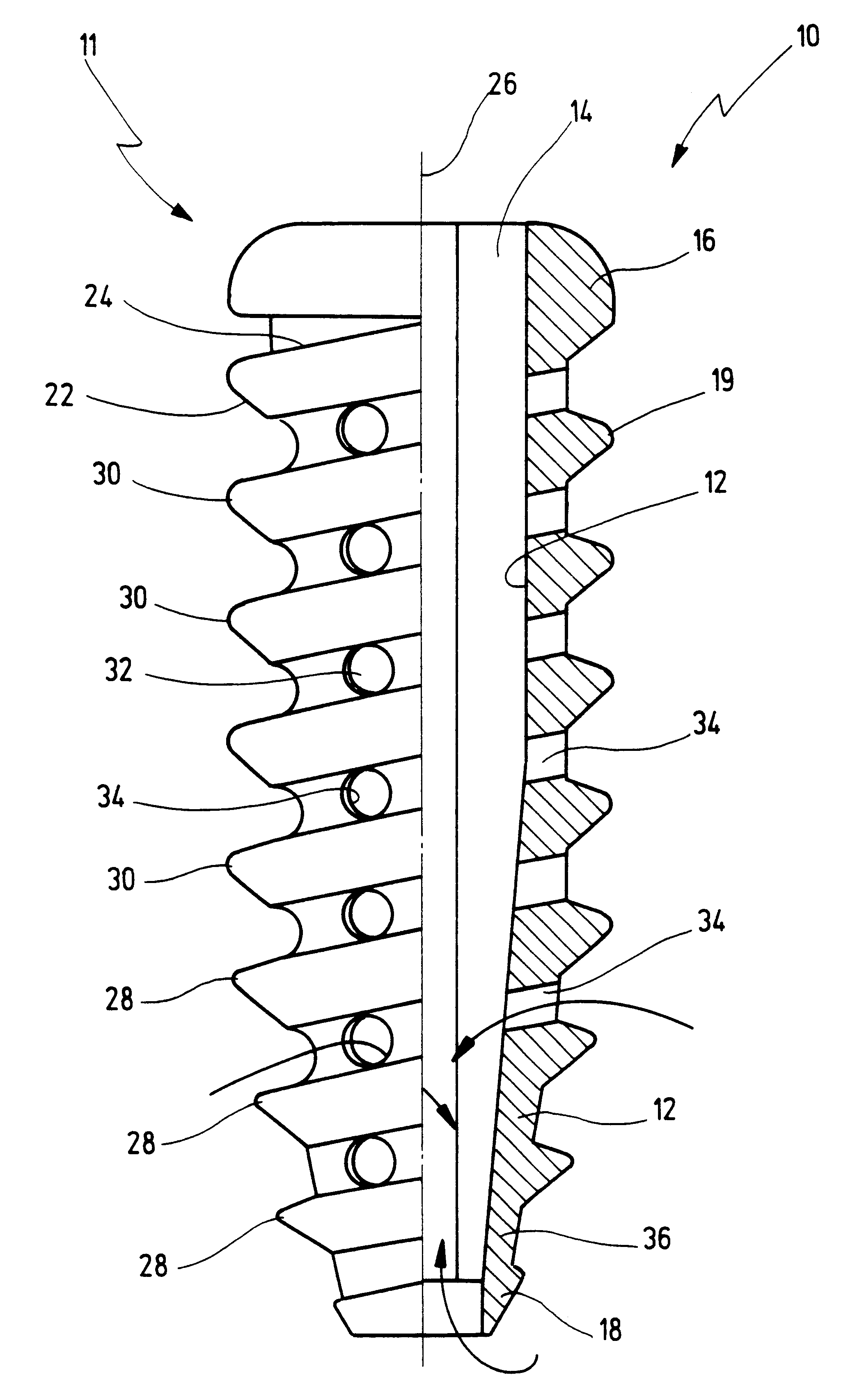
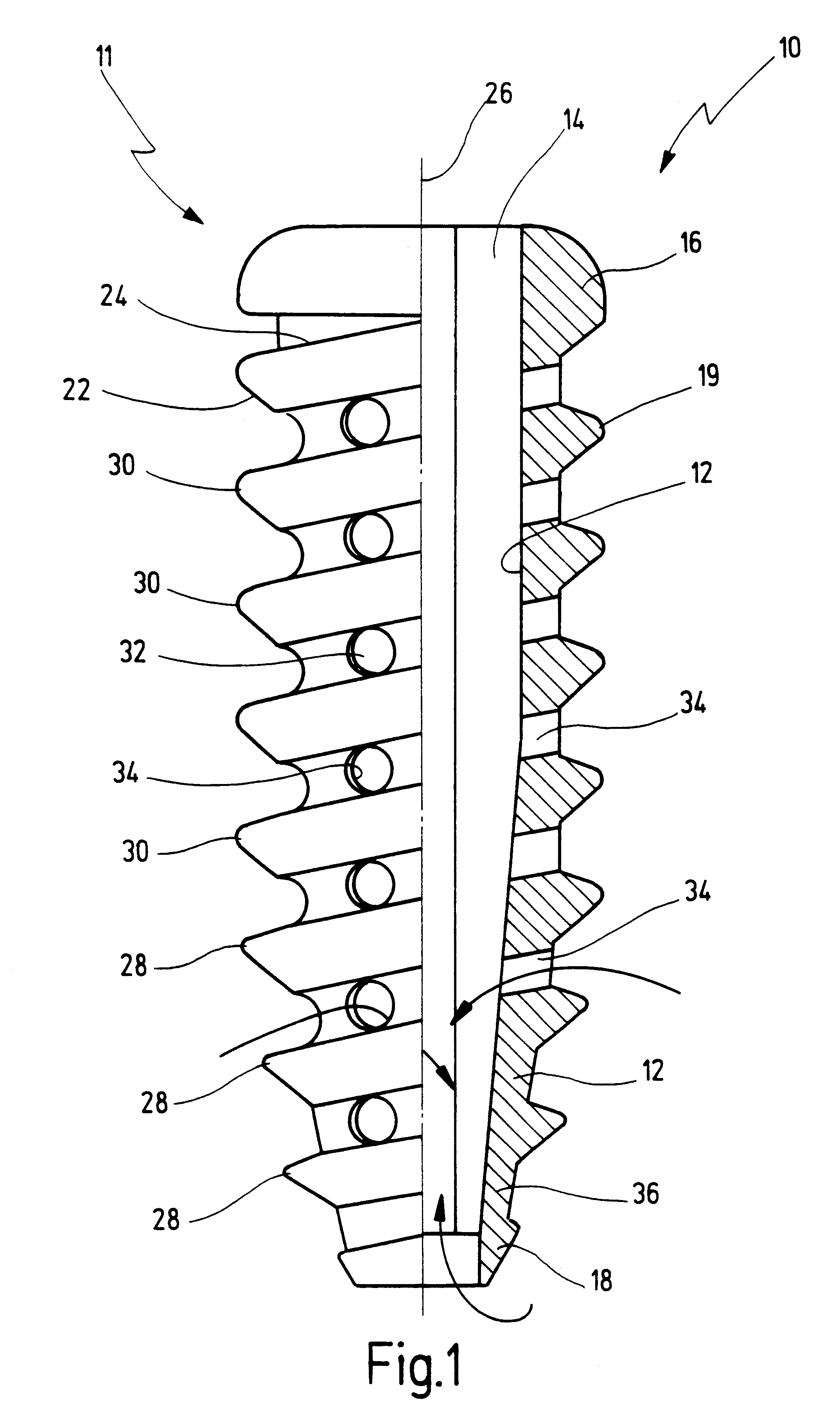
A fixation element is shown in FIG. 1 and designated generally with the reference numeral 10. The element 10 in the present embodiment is formed as an interference screw 11.

The interference screw 11 comprises a body 12 having a head end 16 and a penetrating end 18. The approximately hollow cylindrical screw body tapers in the region of the penetrating end 18. A channel 14 passes completely through the body from the head 16 to the penetrating end 18, whose cross-section at least in the region of the head 16 has a sexangular contour.

The body 12 is provided with anchoring members 19 in the form of an outer threading 20, which extends from the penetrating end 18 to the head 16. The outer threading 20 in the present embodiment is provided with a profile to be a buttress threading. The forward flanks 22 facing the penetrating end 18 have an angle of about 45 degrees with respect to the center axis 26 of the screw 11. The other flanks 24, seen from the head 16 toward the penetrating end 18...


PUM

PropertyMeasurementUnit
angleaaaaaaaaaa
diameteraaaaaaaaaa
outer diameteraaaaaaaaaa

Abstract

A biodegradable fixation element is provided for anchoring a transplant on bone. A rigid body is made of a biodegradable material, said body having an outer side and a hollow interior surrounded by a wall of said body. Numerous perforations are provided in said wall of said body for allowing growth of bone material into said interior of said body via said numerous perforations. It is proposed that the perforations are formed between said anchoring members and said perforations are formed as holes passing through said wall of said body (FIG. 1).

Description

BACKGROUND OF THE INVENTIONThe invention relates to a biodegradable fixation element, in particular for anchoring bone implants, having a body with anchoring elements arranged on its outer side.A biodegradable fixation element in the form of an interference screw is disclosed in OP Journal 14 (1998) pages 278-284 “Biodegradierbare Interferenzschrauben in der Kreuzbandchirurgie” A. Weiler et al., Georg Thieme Verlag Stuttgart, N.Y.Biodegradable materials are ones which are completely absorbed by the body. They also include composite materials which are only partially taken up by the body.Interference screws have the purpose of anchoring a tendon or ligament transplant or implant in a bone. A channel is drilled into the bone in which the transplant is inserted. The interference screw is screwed into the intermediate space between the transplant and the inner wall of the channel, so that the transplant is then clamped between the screw and the inner channel wall.Considerable forces ari...

Claims


Application Information

Patent Timeline
Patent Type & Authority Patents(United States)
IPC IPC(8): A61F2/08A61F2/02
CPCA61F2/0811A61F2002/0841Y10S606/908A61F2002/0882A61F2210/0004A61F2002/0858
Inventor STROBEL, MICHAELWEILER, ANDREASTIMMERMANS, ANDRE
Owner KARL STORZ GMBH & CO KG
Why Eureka
Try Eureka