
Method of assembling plastic filter element with plastic casing

a filter element and plastic casing technology, applied in metal-working devices, electrical devices, domestic applications, etc., can solve the problems of inability to maintain such filter elements, cost-effective manufacture of known filter elements, and inability to manufacture such filter elements, so as to achieve economic and non-sensitive effects

Inactive Publication Date: 2005-03-08
HYDAC FILTERTECHNIK GMBH
View PDF25 Cites 29 Cited by
  • Summary
  • Abstract
  • Description
  • Claims
  • Application Information

AI Technical Summary

Benefits of technology

Objects of the present invention are to provide a filter element which can be manufactured economically, increases the possibility of recycling for the filter element as an entirety, and is not sensitive to the stresses involved in exchanges of the filters.
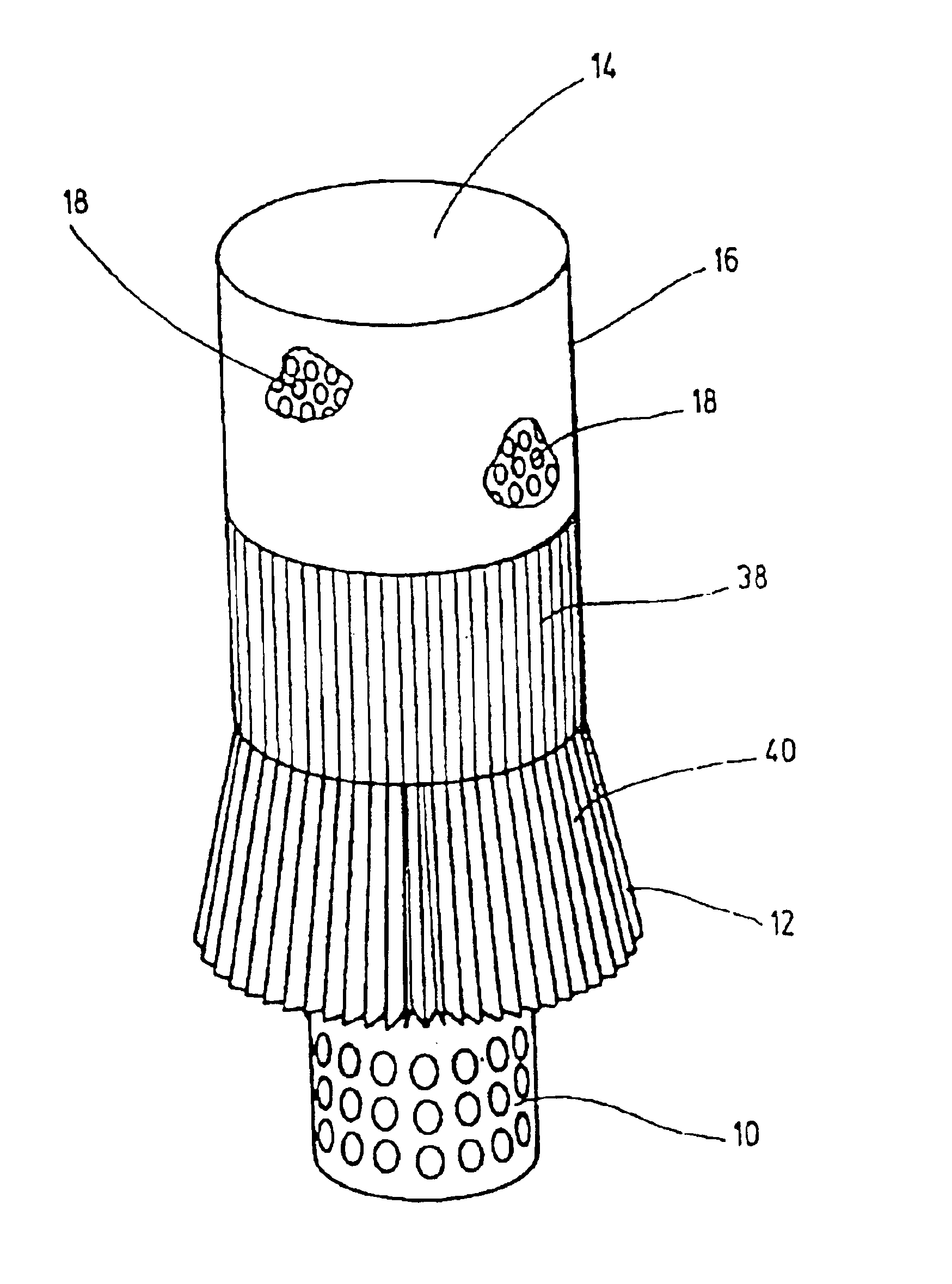
The foregoing objects are basically obtained by a filter element comprising a fluid permeable supporting pipe, a mat filter surrounding the supporting pipe, and a plastic filter casing with opening enclosing the mat filter and delimiting a filter chamber. Two end caps are connected to the filter casing. The mat filter is folded into a cylinder which can be thrust open on the supporting pipe, and has a larger exterior diameter than the interior diameter of the filter casing. The mat filter is brought or extends inward at one of its frontal ends in such a manner that a cone is formed to facilitate its introduction into the cylindrical filter casing. An especially advantageous and economical manufacture of the filter element is attained in this matter. Furthermore, a tightly fitted construction of the mat filter within the filter element is obtained, so that the mat filter can be supported directly on the filter casing and on the supporting pipe and is supported in such a manner that it is not sensitive to the stresses involved in exchanges.
The plastic filter casing is formed of a flat blank, with its edges bent toward one another, defining a sealed filter chamber, and are tightly joined by a sealing seam. The sealing seam can be formed by heat sealing, a heating element or ultrasonic welding. The conventional longitudinal seam clasp for the formation of the sealing seam can be deleted. The high-cost folding back of the ends of the filter casing also need not be executed. The two-component adhesive need not be hardened in the trough-like receiving channel formed by the longitudinal seam clasp. By using a plastic casing as filter casing, and by suitable selection of the plastic material, without further difficulty this arrangement can be heat-sealed together or processed by an ultrasonic welding method. High resistance and stability of the transverse sealing seam is also guaranteed during subsequent operation. The plastic material being used as filter casing can later be disposed of and recycled without problem together with the entire filter element by shredding or the like.
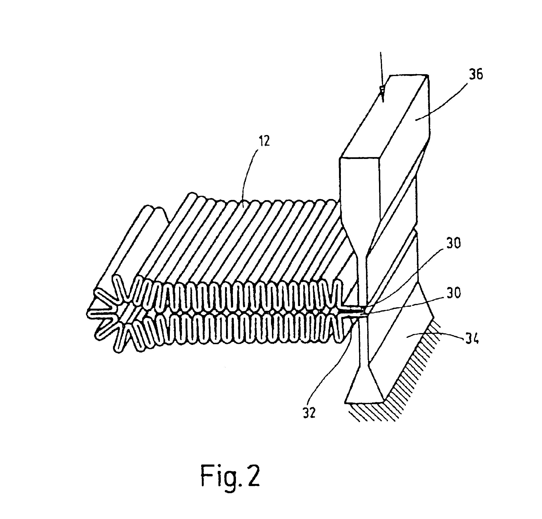
With one especially preferred embodiment of the filter element of the invention the mat filter is pleated and comprises plastic materials. Formation of an additional filter fold and flush alignment of the mat ends one against the other can allow these ends to be tightly joined together with one another by means of an ultrasonic welding method. Since the ends of the filter casing are also connected with one another by means of an ultrasonic welding method, a large part of the relevant sealing for the filter element can be manufactured using such a manufacturing method, saving manufacturing costs.
Providing the mat filter in folds around the cylinder is particularly advantageous in the manufacture of the filter element. The mat filter can be thrust open on the supporting pipe, and provided with a larger exterior diameter than the interior diameter of the filter casing. Preferably, the mat filter is held together at one of its working ends by developing a cone-shape, simplifying its introduction into the cylindrical filter casing.

Problems solved by technology

Because of the plurality of manufacturing stages and the accompanying structural components, the known filter element is costly to manufacture.
Furthermore, there are maintenance problems with such filter elements when they become unusable, especially in relation to the expanded metal casing of metal fabric.
Final maintenance of the filter element, for example when the filter element is to be processed as an entirety in a suitable shredder unit, is consequently not possible and limits the recycling capacity to individual components of the filter element.
However, this application can lead to detrimental thermal stresses for the mat filter.
In this case tolerances occur which interfere with a secure supporting of the mat filter.

Method used


Image

  • Method of assembling plastic filter element with plastic casing
  • Method of assembling plastic filter element with plastic casing
  • Method of assembling plastic filter element with plastic casing

Examples


Embodiment Construction

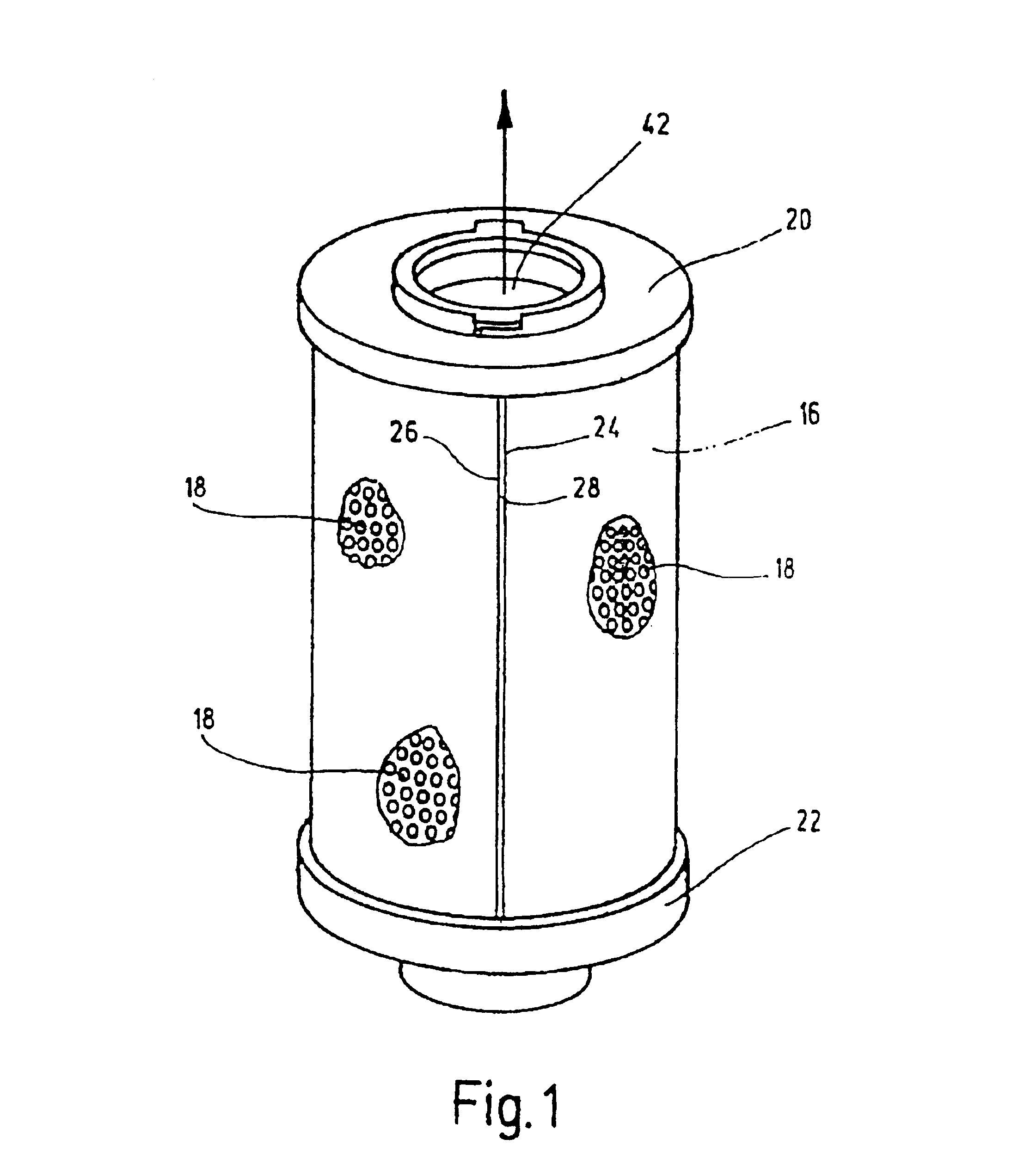
The filter element of FIG. 1 comprises a fluid-permeable supporting pipe 10 (cf. FIG. 5) surrounded by a mat filter 12, which in turn is enclosed by a filter casing 16 with openings 18 delimiting a filter chamber 14. The filter element has end caps 20,22 (cf. FIG. 1).

Supporting pipe 10 is formed of a cylindrical pipe segment and has circular openings for passage of the fluid. The longitudinal ends of supporting pipe 10 are joined together by means of a welding seam, not shown in greater detail.

Supporting pipe 10 is open at the two frontal or axial ends. Filter casing 16 is formed of a plastic, especially of a polyamide or polyethylene compound, with good heat-adhesion properties and / or a good capacity for processing by ultrasonic welding. The plastic filter casing is first formed as a flat blank (not shown). The two ends 24, 26 of the blank are bent around toward one another, and are joined together securely with one another by a sealing seam 28 produced by the aforementioned method...


PUM

PropertyMeasurementUnit
Diameteraaaaaaaaaa
Areaaaaaaaaaaa

Abstract

A method of assembling a filter element includes the initial step of forming a plastic filter casing with openings from a flat blank with opposite ends thereof bent towards one another and joining these opposite ends together by a sealing seam. Also, a resilient mat filter is folded into a cylindrical shape and pushed open on a fluid-permeable supporting pipe to surround and engage the surrounding pipe. The cylindrical shape of the mat filter has an exterior diameter prior to introduction into the casing that is larger than an interior diameter of the filter casing along the entire axial length of the mat filter. The mat folder is folded into a conical shape to facilitate its introduction thereof into the filter casing. After the axial end is formed, the mat filter and supporting pipe are introduced into the filter casing to define a filter chamber. Finally, two end caps are joined to the filter casing.

Description

FIELD OF THE INVENTIONThe present invention relates to a filter element comprising a supporting pipe surrounded by a mat filter. The mat filter is enclosed in a filter casing with openings delimiting a filter chamber. The filter element has two end caps arranged on the frontal surfaces.BACKGROUND OF THE INVENTIONFilter elements disclosed in DE 4312705A1 serve generally to free polluted fluids of pollutants, especially fluids in the form of hydraulic power oil. Pollutants are intercepted by the mat filter of the filter element, and are retained and held out of the fluid current. When the mat filter is filled completely with pollutants, it is exchanged for a new mat filter or the complete filter element is replaced with an entirely new filter element. In this device, the polluted fluid passes through at least one of the two end caps through a corresponding inlet opening into the filter element, and flows through this element for a purification process occurring from the outside inward...

Claims


Application Information

Patent Timeline
IPC IPC(8): B01D46/24B01D46/52B01D29/11B29C65/08B01D46/00B01D29/07
CPCB01D29/111B01D46/0021B01D46/0087B01D46/2411B01D46/521B29C65/08B29C66/1122B29C66/4322B29C66/80B01D46/0001B29C66/4324B01D29/21Y10T29/49945B01D2201/0407B01D2265/022B01D2265/06B01D2275/206B29C66/81433B29L2031/14Y10T156/1038B29C66/8322B29C65/00B29C66/73921B29C66/71B01D46/60B29K2023/06B29K2077/00
Inventor ALTMEYER, GERDMEES, HARALDMOHR, HERBERTLEHMANN, UTE
Owner HYDAC FILTERTECHNIK GMBH
Learn More