
Filter cartridge incorporating a peripheral compatibility matrix

Inactive Publication Date: 2005-03-08
CLARCOR INC
View PDF7 Cites 35 Cited by
  • Summary
  • Abstract
  • Description
  • Claims
  • Application Information

AI Technical Summary

Benefits of technology

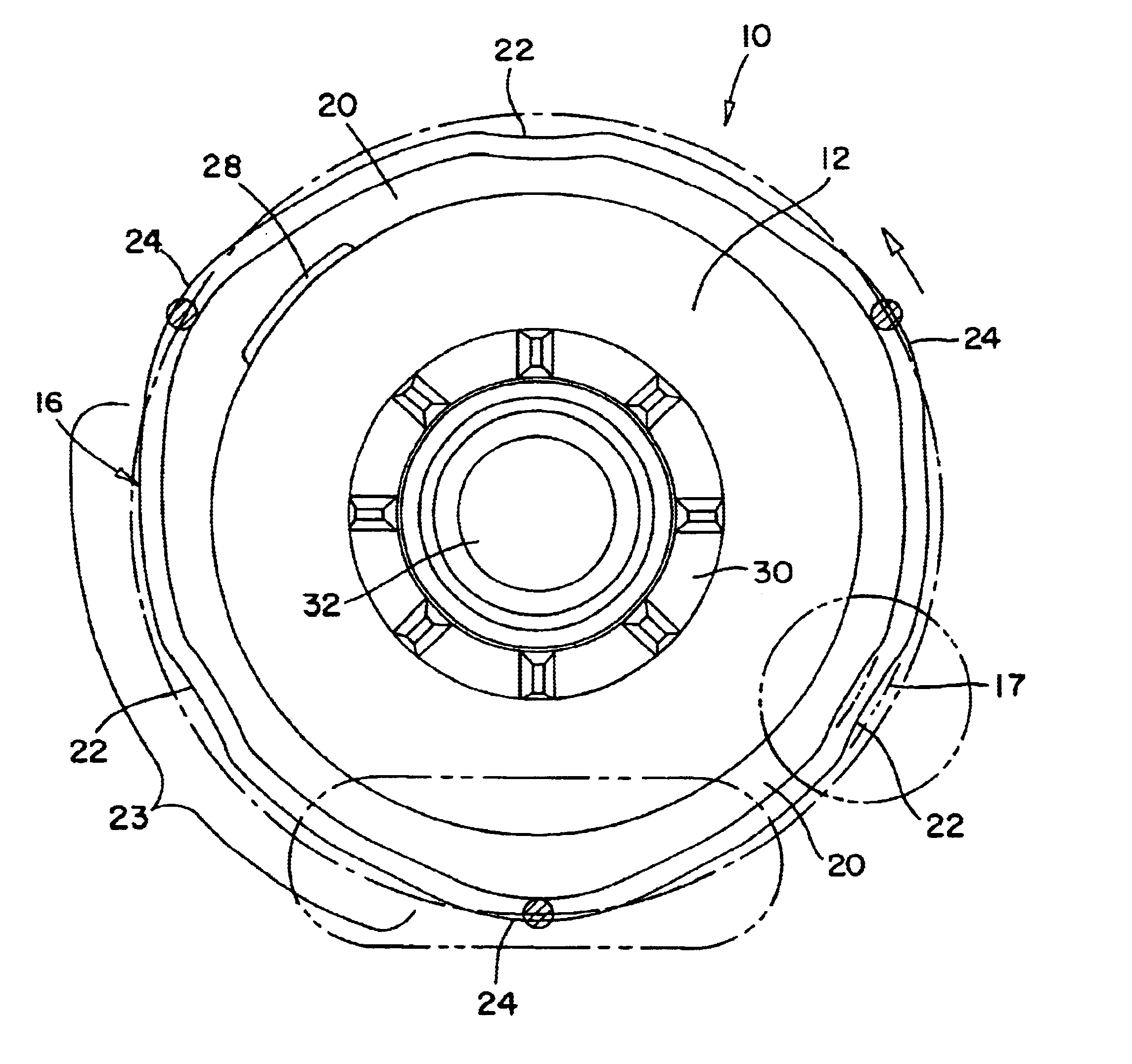
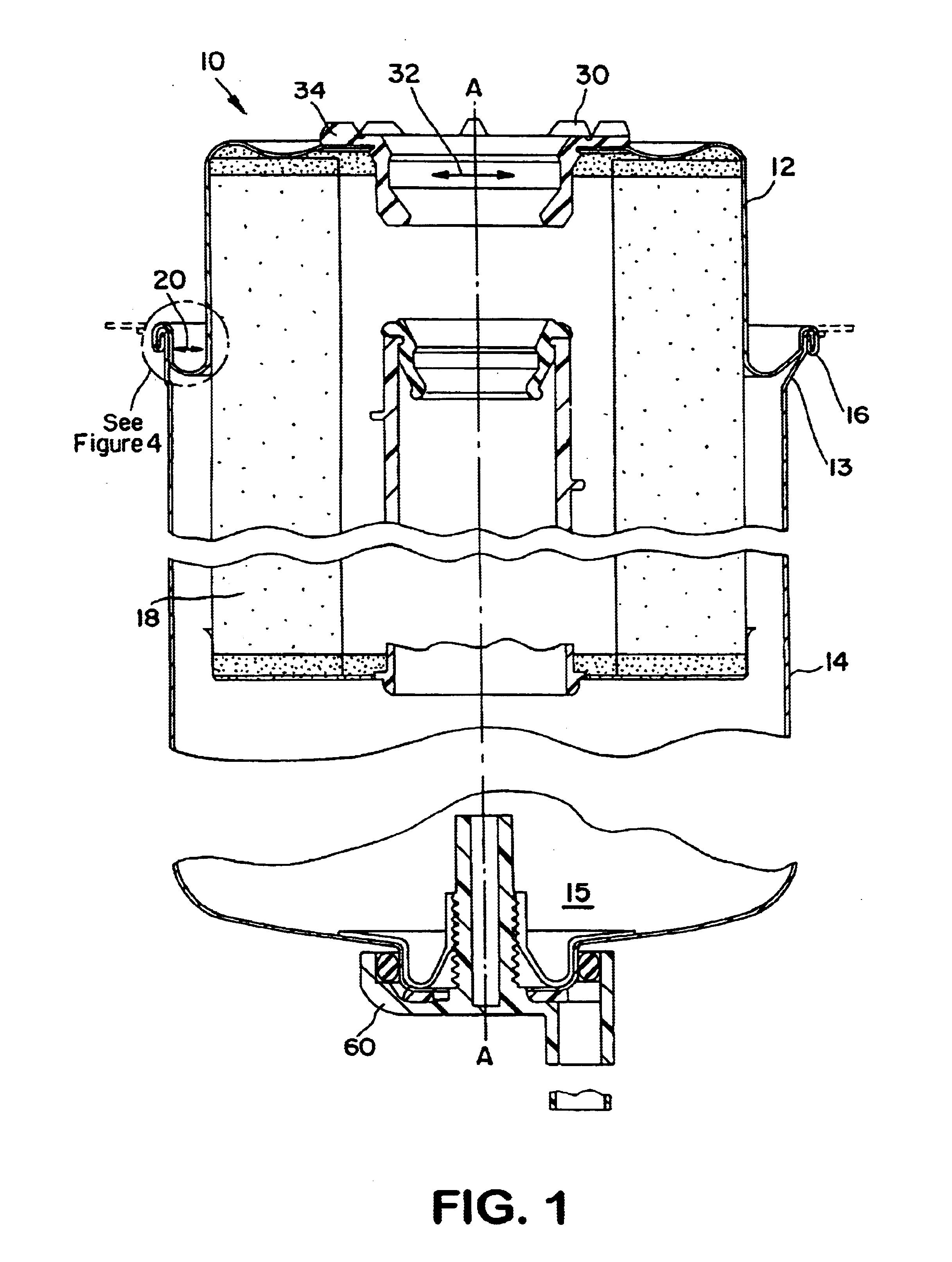
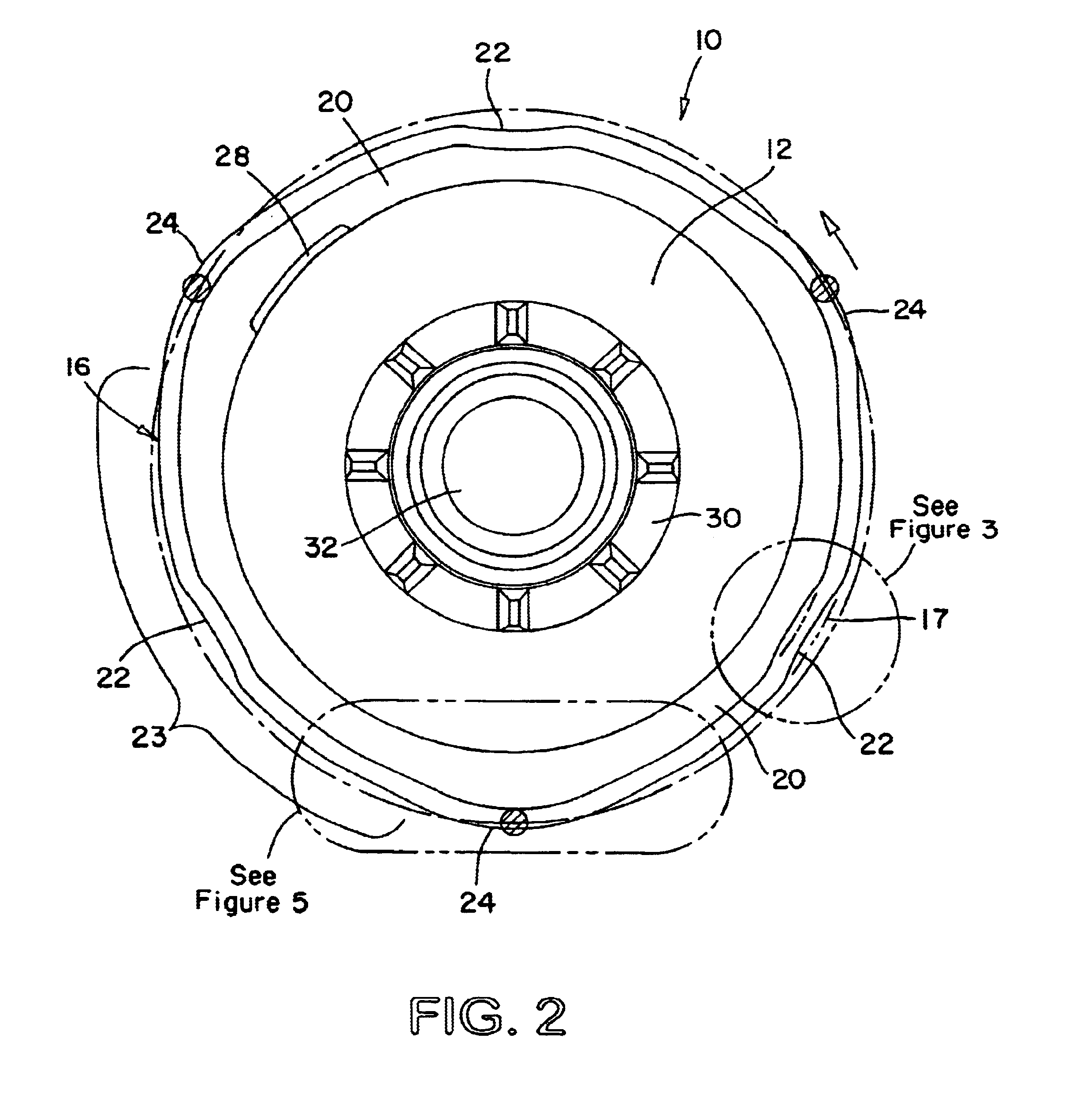
Another aspect of the present invention relates to a filter assembly where a cartridge of the present invention is retained to a base by a collar. An annular lip of the base axially protrudes into a space defined between the roll seam and the received portion of the filter cartridge. The configuration of this space is complementary with the configuration of the roll seam, e.g., the retention tabs increase the radial dimension of the space and the inwardly displaced segments of the roll seam decrease the radial dimension of the space. The axially protruding lip of the base is provided with outward protrusions complementary with the retention tabs and locations where lip material is removed to accommodate inwardly displaced segments of the roll seam.
Another object of the present invention is to provide a new and improved filter cartridge structure that ensures compatibility in filter assemblies having fixed and movable cartridge-retention systems.
A further object of the present invention is to provide a new and improved filter assembly in which compatibility protection cannot be defeated by omission of the compatibility matrix structure from the cartridge.

Problems solved by technology

One of the recurring problems in assuring filtration system performance is encountered in connection with replacement of the filter cartridge.
As a result, a replacement filter cartridge may dimensionally conform to the base of a given fuel filter assembly, and not comply with the applicable specifications for the fuel system and thereby jeopardize the integrity of the fuel filtering system.
Replacement with an incompatible filter cartridge can have very serious consequences for the operation of the internal combustion engine and may also be unnecessarily more expensive than less costly cartridges which are fully suitable.
In practice, replacement cartridges may be so similar in overall configuration that the owner of the vehicle and / or the maintenance technician servicing the internal combustion engine may unknowingly jeopardize the integrity of the filtering system by replacement with a wholly unsuitable cartridge even though the unsuitable cartridge at least cursorily appears to be suitable.
There are also, of course, instances where inferior or improper replacement filter cartridges are intentionally installed without the knowledge of the owner of the operator of the vehicle.
The protrusions interfere with the mounting and sealing of a non-compatible cartridge having an incompatible pattern of dimples.
For example, keys projecting from the base that require openings in the filter cartridge compromise the sealed integrity of the filtration system.
Keying arrangements that restrict the cartridge to a fixed angular position relative to the base are incompatible with filter assemblies that require rotation of the cartridge relative to the base.
The L-shaped tracks disclosed in the '188 patent may be difficult to produce, thereby increasing the cost of filter assemblies.

Method used


Image

  • Filter cartridge incorporating a peripheral compatibility matrix
  • Filter cartridge incorporating a peripheral compatibility matrix
  • Filter cartridge incorporating a peripheral compatibility matrix

Examples


first embodiment

FIGS. 6-11 illustrate one component of a filter base configured to mount the filter illustrated in FIGS. 1-5. The illustrated component 40 of a filter base is a molded member with integrally extending bracket portions 42. The bracket portions 42 are configured to receive a reinforcing metal sleeve (not shown) through which an attachment bolt (not shown) retains the filter base to a support structure (not shown). Below the bracket portions, the illustrated base component 40 comprises a generally cylindrical wall 46 that defines a receptacle 47 for axially receiving the filter cartridge housing first section 12. An axial central conduit 48 of the base component 40 is received and sealingly engaged by a grommet 30 of an installed filter cartridge 10. The cylindrical wall 46 flares to include a fixed integral retainer 44. The retainer 44 comprises three axial slots 51 complementary to the radially projecting retention tabs 24 on the cartridge 10. The axial slots 51 communicate with reta...

second embodiment

The inside surface of the wall 92 defining the receptacle 87 of a filter base component 80 may include axial tracks (not shown) complementary to the pattern of radial protrusions from the cartridge housing first section 12. The tracks may be molded and / or machined on the inner surface of the receptacle of the base component 80. A filter cartridge including an incompatible pattern of radial protrusions will be blocked from axial reception into the receptacle 87. In combination, the configuration of the filter cartridge roll seam 16 and received housing first section 12 can be used to ensure filter compatibility and a particular installed configuration of the filter cartridge 10 relative to the base component 80.


PUM

PropertyMeasurementUnit
Timeaaaaaaaaaa
Angleaaaaaaaaaa
Diameteraaaaaaaaaa

Abstract

A filter assembly employs inward and outward radially displaced portions of a peripheral shoulder on the cartridge as components of a cartridge compatibility matrix. Alternative base assemblies include mounting structures complementary to the configuration of the peripheral shoulder to exclude incompatible cartridges. The peripheral shoulder is preferably a roll seam connecting first and second sections of the filter housing. The invention further contemplates a pattern of radial protrusions from a portion of the cartridge housing received in a base receptacle as part of a cartridge compatibility matrix. The base receptacle is configured to receive only those cartridges having a compatible pattern of radial protrusions. A cartridge compatibility matrix including both inward and outward deformations of a cartridge peripheral shoulder and radial protrusions of the received portion of the cartridge housing can ensure both cartridge compatibility and a particular mounted position of the cartridge relative to the base.

Description

BACKGROUND OF THE INVENTION1. Field of the InventionThis invention relates generally to fuel filters employed in connection with internal combustion engines. More particularly, the present invention relates to replaceable fuel filter cartridges for removing foreign particles and / or separating water from the fuel supply system of an internal combustion engine.2. Description of the Related ArtFuel filter systems to which the invention relates commonly employ a disposable filter cartridge that is replaced at pre-established intervals of filter usage. The replaceable cartridge is conventionally secured to a base that defines inlet and outlet connections between the cartridge and the fuel supply system. Numerous retention systems have been employed for securing the filter cartridge to the base and allowing removal of the cartridge for replacement purposes.In practice, filter cartridge requirements may vary depending upon: the type and make of the internal combustion engine; the specific ...

Claims


Application Information

Patent Timeline
IPC IPC(8): B01D27/08
CPCB01D27/08B01D2201/4015Y10T29/49915Y10S210/17Y10S29/902B01D2201/4046
Inventor JANIK, LEON P.
Owner CLARCOR INC
Learn More