Inverted air box aerator and aeration method for immersed membrane

a technology of aerator and aeration method, which is applied in the direction of membranes, multi-stage water/sewage treatment, separation processes, etc., can solve the problems of increasing equipment cost and energy required to produce bubbles, and the air flow per hole is not sufficient to prevent tank water from flowing, so as to reduce the volume of the air pocket

Inactive Publication Date: 2005-03-08
ZENON TECH PARTNERSHIP
View PDF19 Cites 86 Cited by
  • Summary
  • Abstract
  • Description
  • Claims
  • Application Information

AI Technical Summary

Benefits of technology

Air may be provided to the aerator shell at the higher flow rate during about ⅛ to ½ of each cycle. When air is provided at a higher rate of air flow, the aerator traps a pocket of air which grows in volume and releases bubbles from its upper surface. When air is provided at the lower rate of air flow, the aerator may continue to release bubbles from its upper surface and the volume of the air pocket decreases. Bubbles may be released during about ⅓ to ⅔ of the cycle duration. The aerator may become partially or completely flooded during a later part of the lower air flow period to help remove accumulated solids. Alternately, bubbles may be produced throughout each cycle.
In other aspects of the invention, a filtration system, which may be used to extract drinking water from a water to be filtered, has one or more immersed membranes assemblies, or modules, located in a

Problems solved by technology

The shroud and deep aerators increase both the equipment cost and the energy required to produce bubbles.
Although the large number of holes provides well distributed bubbles, the air flow per hole is not sufficient to prevent tank water

Method used


Image

  • Inverted air box aerator and aeration method for immersed membrane
  • Inverted air box aerator and aeration method for immersed membrane
  • Inverted air box aerator and aeration method for immersed membrane

Examples


Embodiment Construction

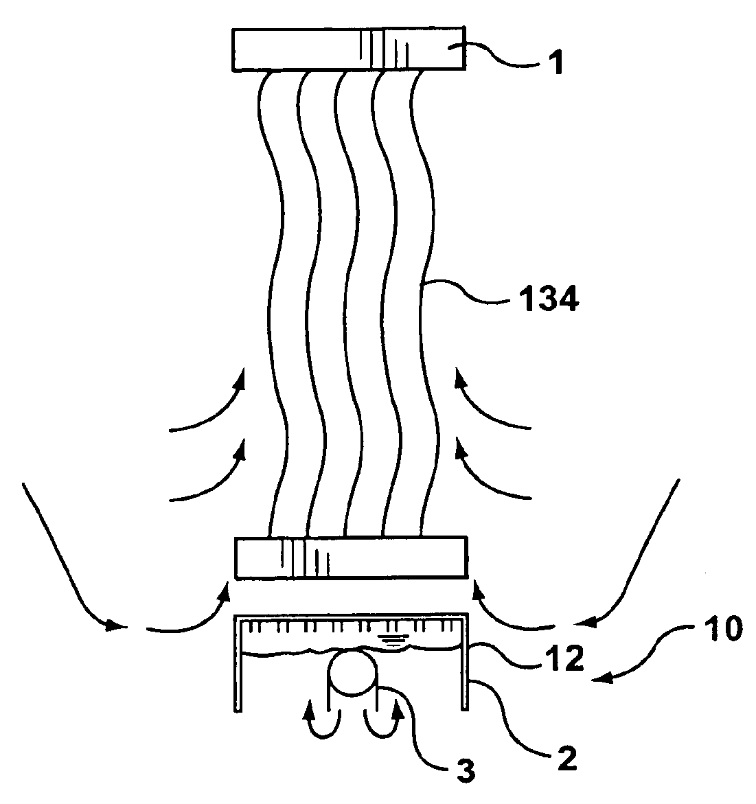
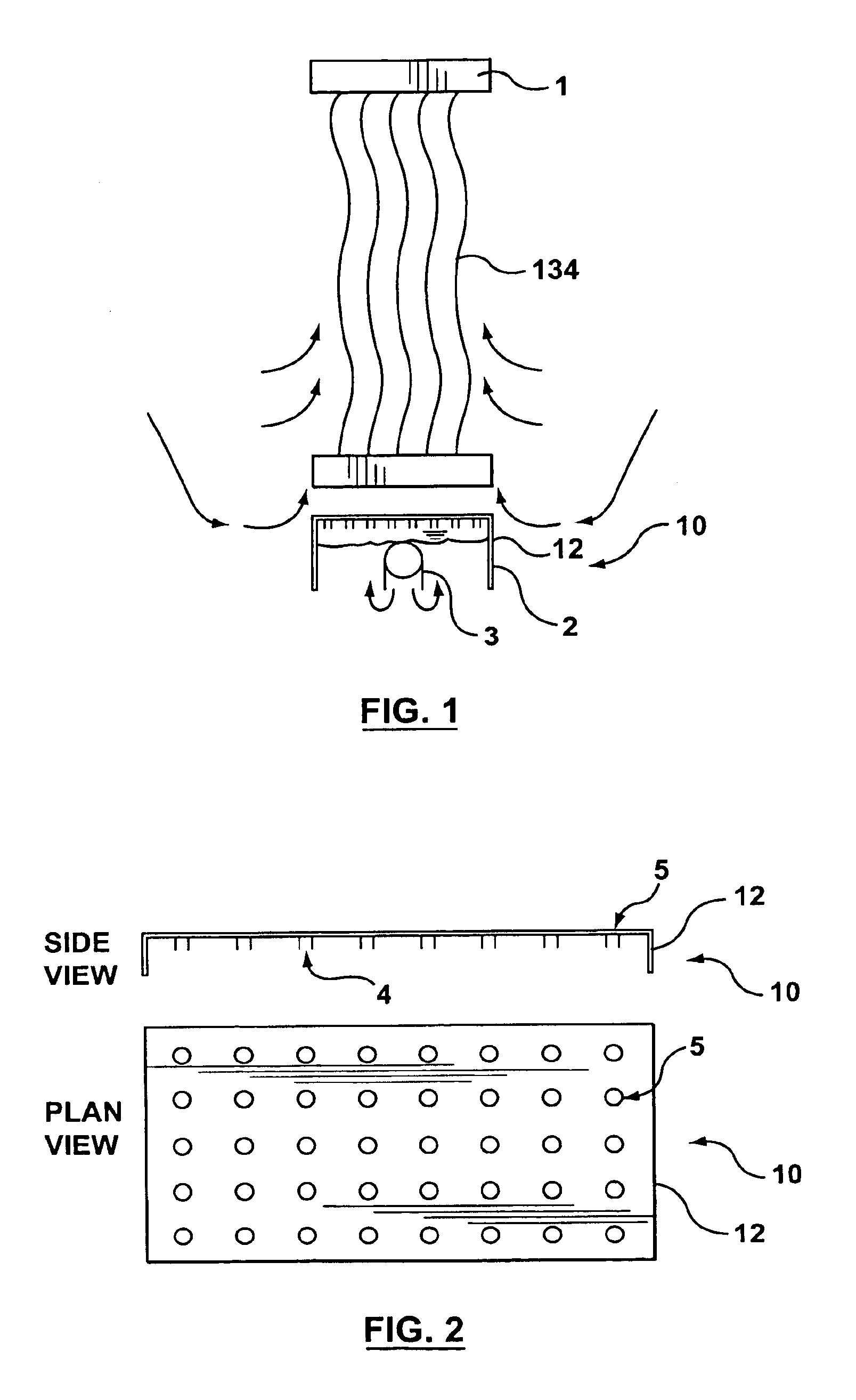
FIGS. 1 and 2 show a first aerator 10 having an aerator shell 12 in the shape of an inverted box which will be called an air box 2. Referring to FIG. 1, the air box 2 is located below at least one membrane assembly 1. The first aerator 10 may also service a plurality of membrane assemblies 1, for example four to sixteen, or more, membrane assemblies 1. A space between the membrane assembly 1 and the air box 2 optionally promotes liquid recirculation through and about the membrane assembly 1. Alternately, the space may be reduced or eliminated to preserve space when the air box 2 is used with the filtration system described further below.

The air box 2 may be rectangular or other shapes capable of supporting holes 5 in desired locations in an upper surface, at least temporarily containing a variable volume of air in communication with the holes 5 and open to tank water so that tank water can be displaced from or enter into the air box 2 as the volume of contained air changes. The air ...


PUM


Abstract

An aerator for immersed filtering membranes has an aerator shell with openings for discharging bubbles from its upper surface and a shape capable of temporarily containing a volume of air in fluid communication with the openings. The shell is open to tank water below it and located so that discharged bubbles will rise through an assembly of the filtering membranes. The shell may be wholly or partially made of parts of the assemblies of filtering membranes. A supply of air is provided to the air space in the aerators alternating between a high flow rate and a low flow rate in short cycles of between about 10 seconds and 100 seconds. A filtration system has an inlet for adding substrate and an outlet for retentate are located so as to create a horizontal flow of substrate through the tank. Membrane assemblies are located within the horizontal flow of substrate. Aerators as described above are provided and operated as described above.

Description

FIELD OF THE INVENTIONThis invention relates to an aerator, aerating method and filtration system for immersed membranes.BACKGROUND OF THE INVENTIONAeration is used with immersed membranes to scour the membranes and to disperse areas of tank water having increased concentrations of rejected solids from near the membranes. An ideal aeration system for immersed membranes would scour the entire assembly of membranes with minimum energy use, cost and maintenance required to keep the aerators from plugging.U.S. Pat. Nos. 5,192,456 and 5,482,625, issued on Mar. 9, 1993 and Jan. 9, 1996 to Kubota Corporation, describe an air diffuser disposed below a set of membrane cartridges. A casing surrounds the air diffuser and the membrane cartridges, extending vertically from the bottom of the diffuser to the top of the membrane cartridges. In commercial embodiments, the diffuser is locater about 1 m below the membrane cartridges and the diffusers provide a small number of holes per square metre of...

Claims


Application Information

Patent Timeline
IPC IPC(8): B01D65/08B01D65/02B01D61/20B01D61/18B01D65/00C02F3/20C02F1/44
CPCB01D61/18B01D61/20B01D65/02B01D65/08C02F1/444C02F3/20B01D2315/06Y10S261/70B01D2321/185C02F2303/16B01D2321/02Y02W10/10
Inventor COTE, PIERRE
Owner ZENON TECH PARTNERSHIP
Why Eureka
Try Eureka