Fixing device for image forming apparatus

a technology of fixing device and image forming apparatus, which is applied in the direction of electric/magnetic/electromagnetic heating, manufacturing tools, instruments, etc., can solve the problems of reducing the warm-up time, long waiting time, and low durability, and achieves efficient heat transmission

Inactive Publication Date: 2005-03-08
MINOLTA CO LTD
View PDF15 Cites 28 Cited by
  • Summary
  • Abstract
  • Description
  • Claims
  • Application Information

AI Technical Summary

Benefits of technology

1. A primary object of the present invention is to provide a fixing device of fixing-belt type which is capable of promptly heating the fixing belt to an operating temperature proper for a fixing process by using a heating plate with a novel structure which allows efficient heat transmission to the fixing belt.

Problems solved by technology

The aforementioned conventional fixing device of fixing-roller type has the disadvantage of a long waiting time from the time of power-on until a temperature at which a fixing process can be performed is reached in addition to the problems of large energy consumption for constantly holding the heating roller at a high temperature and temperature elevation within the fixing device due to heat dissipation from the fixing device into an image forming apparatus even during standby.
Because of the large heat capacity, the heat of the belt is partly taken by the rollers so that the reduction of a warm-up time is approaching a limit even if efficient heating is performed by electromagnetic induction.
However, the approach has the problem of low durability since the surface in sliding contact with the heater is a fixing surface and therefore is prone to flaws.
However, since a heater is required to have a pressing function and a heating function, the nip portion cannot have a sufficiently large width.
In addition, the problem of high cost is also encountered since highly accurate dimensions and assembly are required of a heater holding member and the heater.
In the foregoing fixing device of fixing-belt type using the semi-cylindrical heating plate, however, the inner surface of the semi-cylindrical heating plate is open so that heat is radiated uselessly.
The radiated heat not only reduces heat efficiency but also renders the fixing device unsatisfactory in terms of safety.
In inspecting the fixing device, the inspector may suffer a burn by mistake.

Method used


Image

  • Fixing device for image forming apparatus
  • Fixing device for image forming apparatus
  • Fixing device for image forming apparatus

Examples


first embodiment

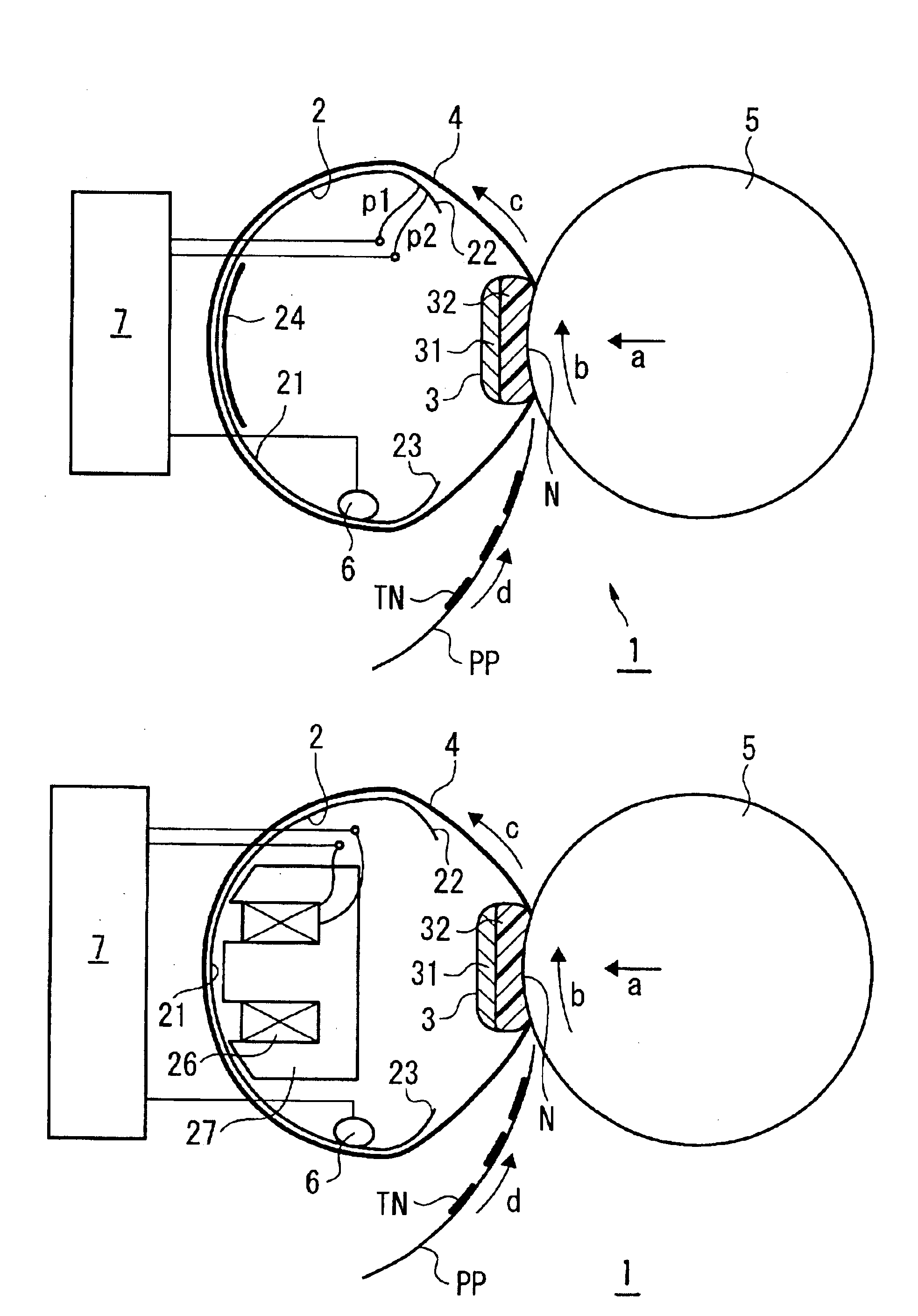
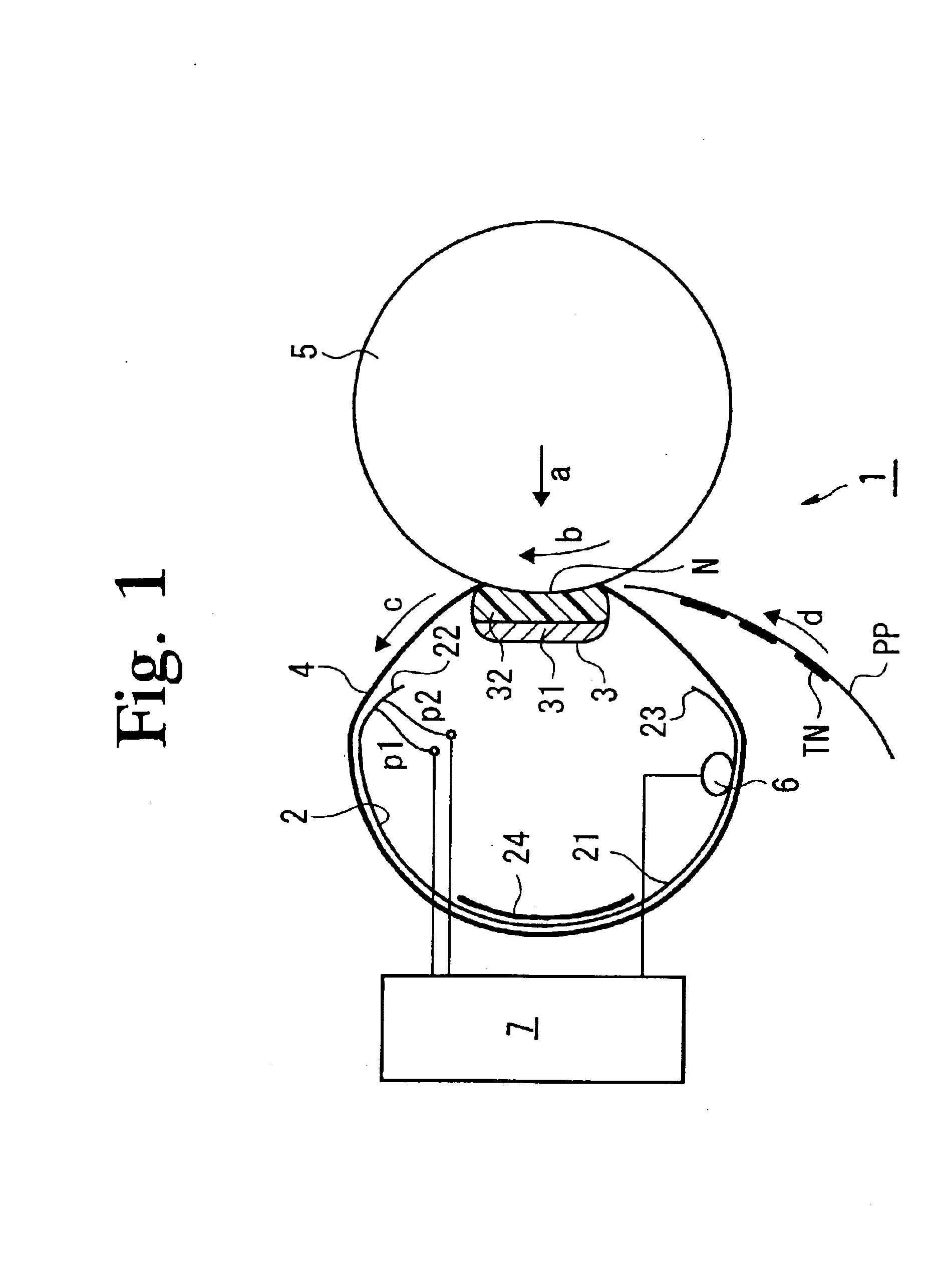
FIG. 1 is a cross-sectional view of a belt-type fixing device according to a first embodiment of the present invention. The belt-type fixing device 1 comprises: a heating plate 2; a pressing pad 3; a fixing belt 4; a pressing roller 5; a temperature sensing unit 6; and a control unit 7.

The fixing belt 4 is entrained about the pressing pad 3 and the heating plate 2 in a properly tensioned condition. The pressing pad 3 is composed of an elastic member 32 such as a heat resistant sponge fixed onto a rigid support member 31. A biasing force for pressing the fixing belt 4 against the pressing pad 3, as indicated by the arrow a, has been imparted to the pressing roller 5. The biasing force deforms the elastic member 32 and the fixing belt 4 into configurations conformal to the circular cross-sectional configuration of the pressing roller 5 so that a nip portion N is formed.

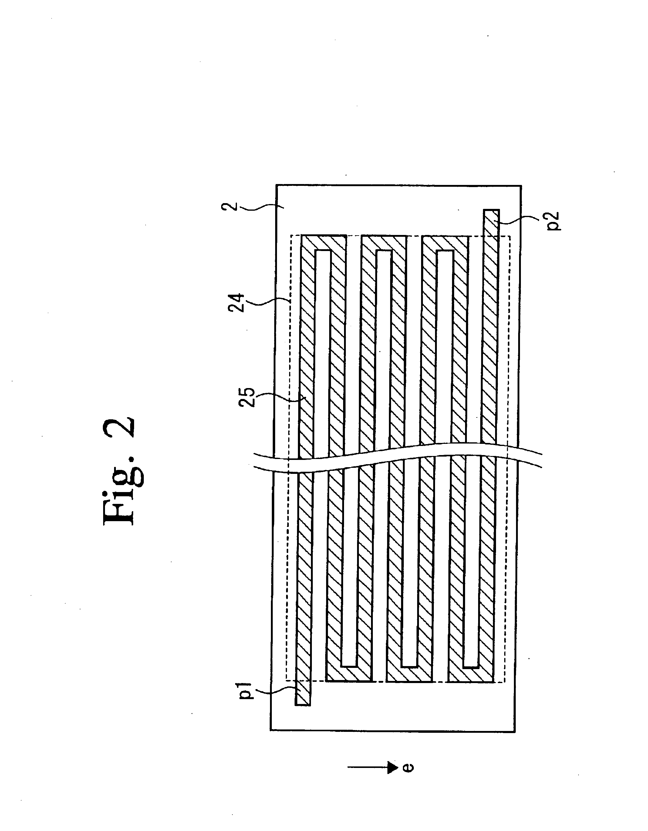
The heating plate 2 comprises: a cylindrical surface portion 21 having a nearly circular configuration; inwardly curv...

second embodiment

FIG. 3 is a cross-sectional view of a belt-type fixing device 1 according to a second embodiment of the present invention. The belt-type fixing device 1 comprises: a heating plate 2, a pressing pad 3, a fixing belt 4, a pressing roller 5, a temperature sensing unit 6; and a control unit 7, similarly to the first embodiment. The second embodiment is different from the first embodiment in that the heating plate 2 is induction heated by an electromagnetic induction coil 26. Accordingly, the heating plate 2 is composed of a metal material, such as iron or stainless steel, which can be induction heated. It is to be noted that the heating plate 2 is not provided with the resistance heat generator 25. The description of the components common to the first embodiment is omitted by retaining the same reference numerals.

The electromagnetic induction coil 26 is wound around the center iron core of an E-shaped core 27 to have an open end located in proximity to the cylindrical surface portion 21...

third embodiment

The third embodiment of the present invention will be described. FIGS. 7(a) to 7(c) are views each illustrating a structure of a fixing device according to the third embodiment, of which FIG. 7(a) is a perspective view of a structure of a fixing belt assembly, FIG. 7(b) is a perspective view of a pressing roller assembly, and FIG. 7(c) is a perspective view of the fixing device completed by mounting the pressing roller assembly on the fixing belt assembly. FIG. 8 is a front view of the fixing device shown in FIG. 7. FIG. 9 is a cross-sectional view taken along the line A—A of the fixing device shown in FIG. 8.

A description will be given herein below with reference to FIGS. 7(a) to 7(c), FIG. 8, and FIG. 9. The fixing device 40 is composed of the fixing belt assembly 41 and the pressing roller assembly 51. The fixing belt assembly 41 is provided with a heating plate 46 composing a heater and a fixing belt 49 composing a fixing rotator. The pressing roller assembly 51 is provided with...


PUM

PropertyMeasurementUnit
thicknessaaaaaaaaaa
sheet-like resistanceaaaaaaaaaa
pressureaaaaaaaaaa

Abstract

A belt-type fixing device for an image forming apparatus is capable of raising a temperature to a level suitable for a fixing process in a short period of time with high heating efficiency. A fixing belt is entrained in spanning relation between a heating plate providing a heat generator on the inner surface of the semi-cylindrical plate and a pressing pad disposed at a distance from the heating plate. A pressing roller is disposed at a position opposing the pressing pad. The fixing belt is revolved by rotating the pressing roller. A recording medium having a toner adhered thereto is caused to pass through a nip portion of the fixing belt and the pressing roller.

Description

This application is based on application(s) No(s). 2002-90472, 2002-218102, and 2002-218457 filed in Japan, the contents of which are hereby incorporated by reference.BACKGROUND OF THE INVENTION1. Field of the InventionThe present invention relates to a fixing device for an electrophotographic image forming apparatus such as an electrophotographic copier or printer.2. Prior ArtIn a conventional electrophotographic image forming apparatus such as an electrophotographic copier or printer, a latent image of an original image is formed by uniformly charging a photosensitive member and exposing the original image on the photosensitive member. The formed latent image is developed with a toner to form a toner image of the original image, which is transferred onto a recording medium or transferred onto an intermediate transfer member and then further transferred onto the recording medium. The transferred toner image is subjected to a heat fixing process performed by a fixing device, whereby...

Claims


Application Information

Patent Timeline
Patent Type & Authority Patents(United States)
IPC IPC(8): G03G15/20
CPCG03G15/2064G03G2215/2016G03G2215/2035G03G2215/2029
Inventor OKABAYASHI, EIJIKIDOKORO, TAKASHI
Owner MINOLTA CO LTD
Why Eureka
Try Eureka