Any way of interconnecting the first elevation member with the substrate in a manner that allows a free end thereof to at least generally move away from or toward the substrate may be utilized. The first elevation member may be compliantly attached to the substrate such that the portion of the first elevation member between the first location and its free end is able to rotate or “pivot” about this connection point, and thus allow this free end to move at least generally away from or toward the substrate with a displacement that has both a component that is lateral to the substrate and a component that is perpendicular to the substrate (e.g., along an arcuate path). In one embodiment, a portion of the first elevation member is connected directly to the substrate at the first location, and the first elevation member “bends” or flexes to provide the desired motion for the free end of the first elevation member at least generally away from or toward the substrate. In this configuration, the first elevation member may have first and second cross-sectional areas along its length. As will be appreciated, if the entire first elevation member is made of the same material (e.g.,
polycrystalline silicon) and in the same structural layer, the portion of the first elevation member with the smaller cross-sectional area will have a smaller
moment of inertia about a particular axis and, thus, will be less stiff than the larger cross-sectional area portion. Accordingly, this smaller cross-sectional portion may be formed over that portion of the first elevation member that is attached to the substrate and act as what may be characterized as an integral flexible / compliant hinge, thereby allowing the free end of the first elevation member to move at least generally away from or toward the substrate.
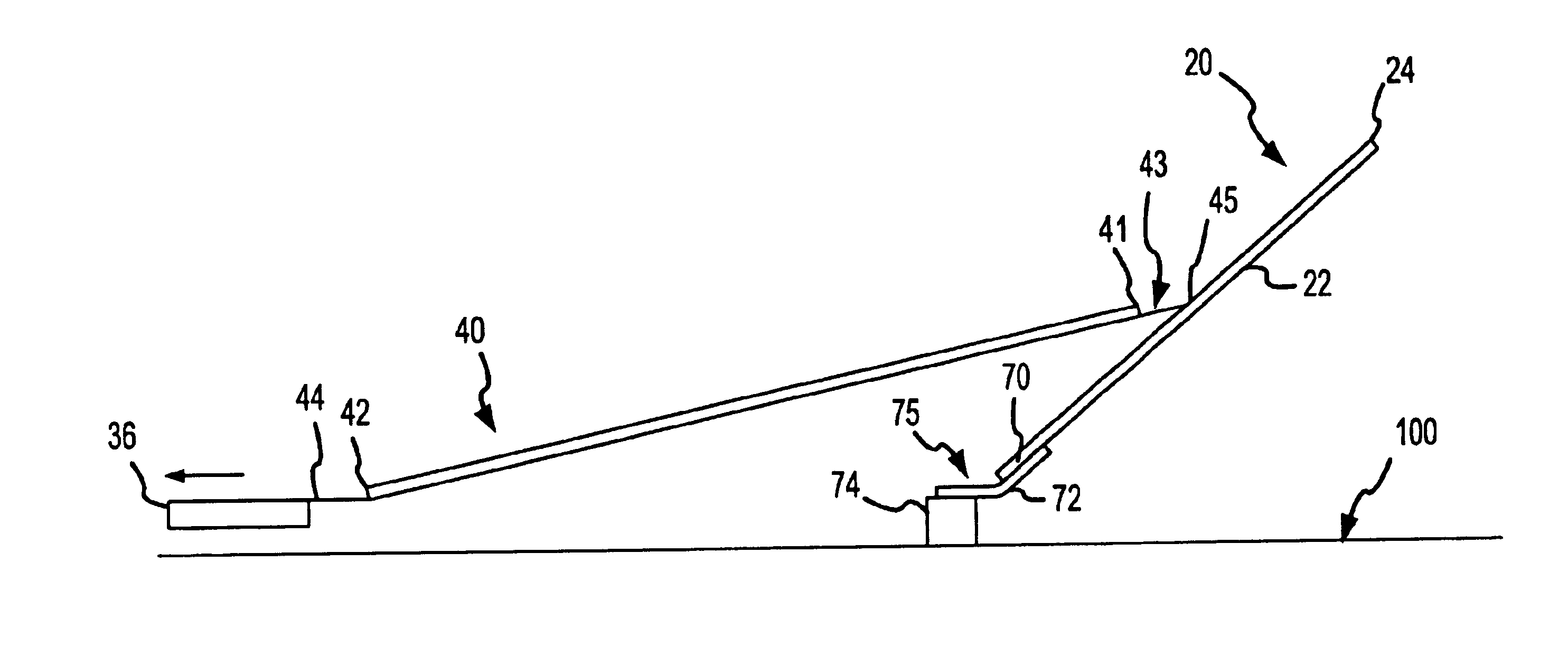
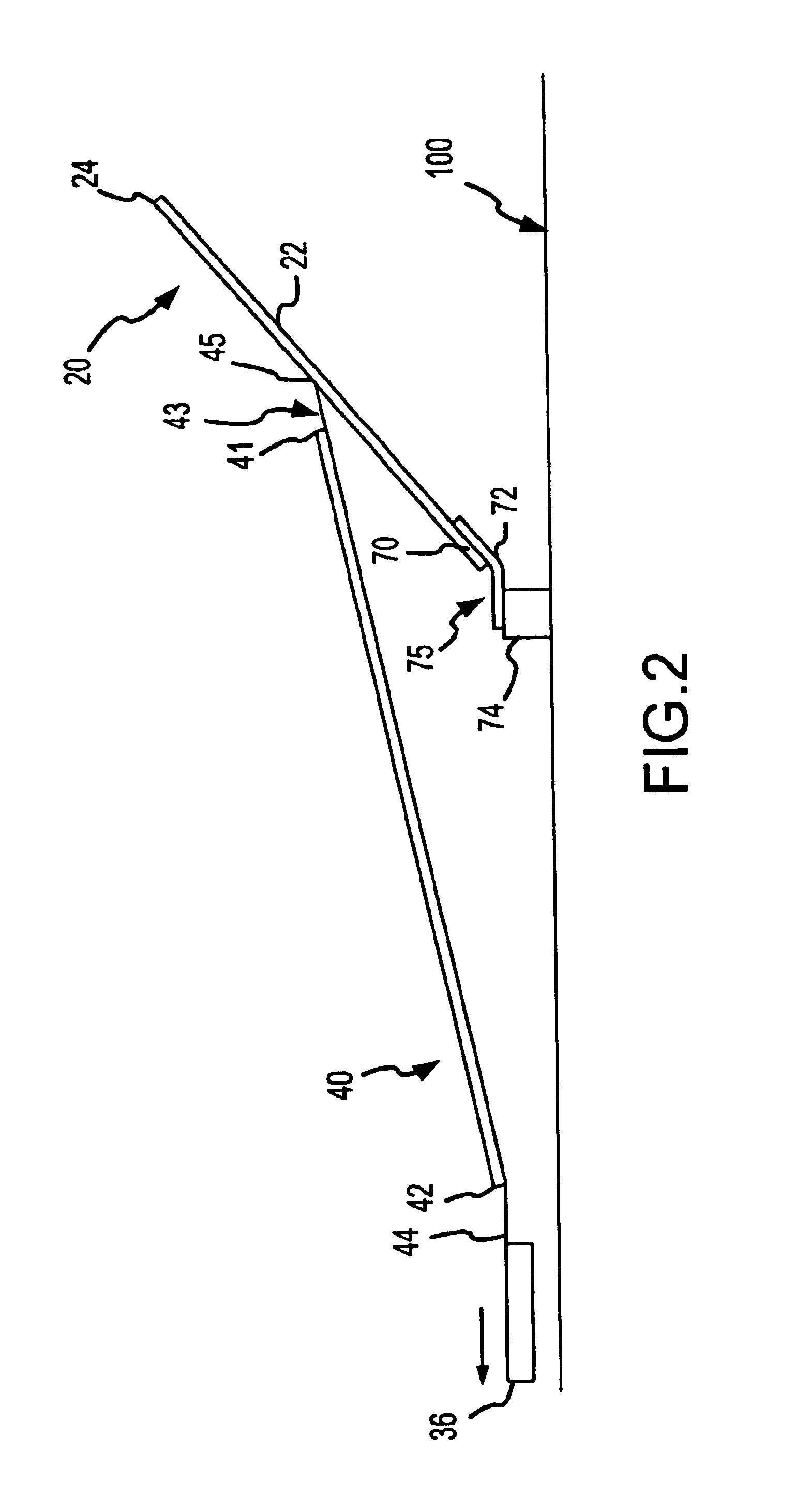
Any appropriate configuration for the first elevation member may be utilized by the first aspect of the present invention, as well as any manner of movably interconnecting the same with the substrate. For instance, the first elevation member could be a single simple beam. Another option would be to define the first elevation member by a plurality of legs or beams that are appropriately interconnected. One or more cross beams may extend between and interconnect two or more of these legs to provide a desired degree of rigidity to the first elevation member.
The MEM system of the third aspect of the present invention is preferably fabricated by
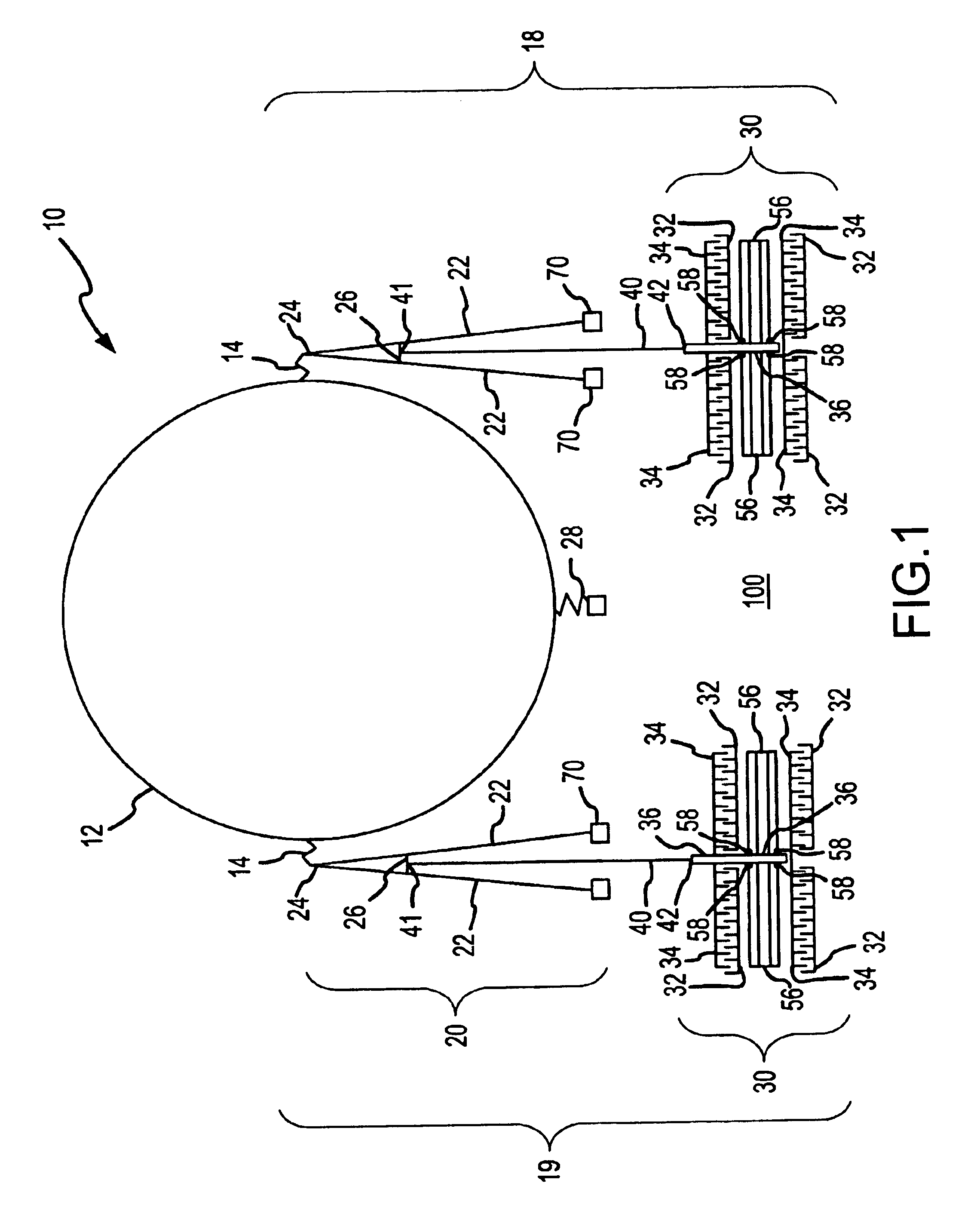
surface micromachining, although other fabrication techniques or combination of fabrication techniques may be utilized as desired / required. In any case, the MEM system of the third aspect includes a substrate, an actuator assembly that is movably interconnected with the substrate in any appropriate manner, a first lever that is interconnected with the substrate for movement at least generally about a first location and that has a first free lever end that is movable relative to the substrate at least generally about the first location, and an elongate
coupling or “tether” that is disposed between and interconnects the actuator assembly and the first lever (either directly or indirectly). Any configuration may be used for this tether. What is important is that the tether is sufficiently stiff so as to withstand the external forces applied thereto without substantially bowing or buckling.
The benefit of using a tether that is sufficiently stiff to withstand the external forces that may be applied to the tether due / in response to a movement of the actuator assembly (including how the motion of the actuator assembly is initiated and / or maintained, as well as how the motion of the actuator assembly is terminated) in accordance with the third aspect is that a slapping and / or oscillatory effect associated with less stiff tethers is eliminated or at least significantly reduced. For example, a tether that will flex or bow when exposed to external forces of at least a certain magnitude will result in
elastic energy being stored within the tether. When this
elastic energy is released, this may cause a free end of the lever to accelerate in an undesired manner, may cause this free end of the lever to vibrate or oscillate, or both. The release of this
elastic energy may significantly adversely affect the ability to precisely control the operation of the microelectromechanical system, may cause undesired contact between components of the microelectromechanical system and possibly resulting structural damage, or both. Using a stiff tether (such that no significant elastic energy is stored in the tether as a result of typical external forces being exerted thereon) in accordance with the third aspect addresses these types of deficiencies. Stiff tethers also may allow for increasing the switching speed in the case where the third aspect is used in an optical application (e.g., when a mirror
microstructure is interconnected with a portion of the first lever that is movable relative to the substrate).
One
advantage of the configuration of the connector that is utilized by the seventh aspect is that it enhances one or more aspects of the manner in which the motion of the
coupling is transferred to the lever assembly. As discussed above in relation to the fourth, fifth, and sixth aspects, certain configurations for the coupling also may provide one or more advantages in relation to the transfer of forces to an elevation structure. Therefore, any of the features discussed above in relation to one or more of the fourth, fifth, and sixth aspects of the present invention may be used alone or in any combination with the subject seventh aspect (and vice versa).

