Welding power supply transformer

Inactive Publication Date: 2005-03-08
ILLINOIS TOOL WORKS INC
View PDF38 Cites 12 Cited by
  • Summary
  • Abstract
  • Description
  • Claims
  • Application Information

AI Technical Summary

Benefits of technology

According to a fifth aspect of the invention, a method of reducing the leakage inductance in a welding-type power supply transformer includes providing a first coil. A second coil is wou

Problems solved by technology

Having coil windings with rectangular or square cross sections can be problematic in welding applications however.
This is because the large diameter wires used in welding power supply transformers have a tendency to deform or bulge at locations where the winding direction changes quickly (e.g., at the corners when wound around a bobbin having a square or rectangular cross section).
As a result, the coil may not fit within the winding window of the bobbin in those areas.
Another problem with using large diameter wires in welding power supply transformers is that the wire leads to and from these transformers tend to be less flexible than smaller wire leads.
The current trend in designing welding power supplies, plasma cutters and induction heaters, however, is to make these devices smaller.
Another problem with welding power supply transformers, especially welding power supply transformers operating at high frequencies, is leakage inductance.
The presence of high leakage inductance in these transformers can cause several problems.
The primary and secondary coils in leaky transformers are more susceptible to overheating.
Finally, the energy stored in the leakage inductance can be detrimental to transistor switching circuits in the welding power supply.
Release of this stored energy can cause ringing, transistor failure and timing issues.

Method used


Image

  • Welding power supply transformer
  • Welding power supply transformer
  • Welding power supply transformer

Examples


Embodiment Construction

While the present invention will be illustrated with reference to a particular electrical transformer configuration having particular features, the present invention is not limited to this configuration or to these features and other configurations and features can be used. Similarly, while the present invention will be illustrated with reference to a welding power supply having a particular configuration and particular features, other welding and non-welding power supplies having other configurations and features can also be used. Finally, the present invention is also not limited to use in power supplies, but rather can be used in other non-power supply applications as well.

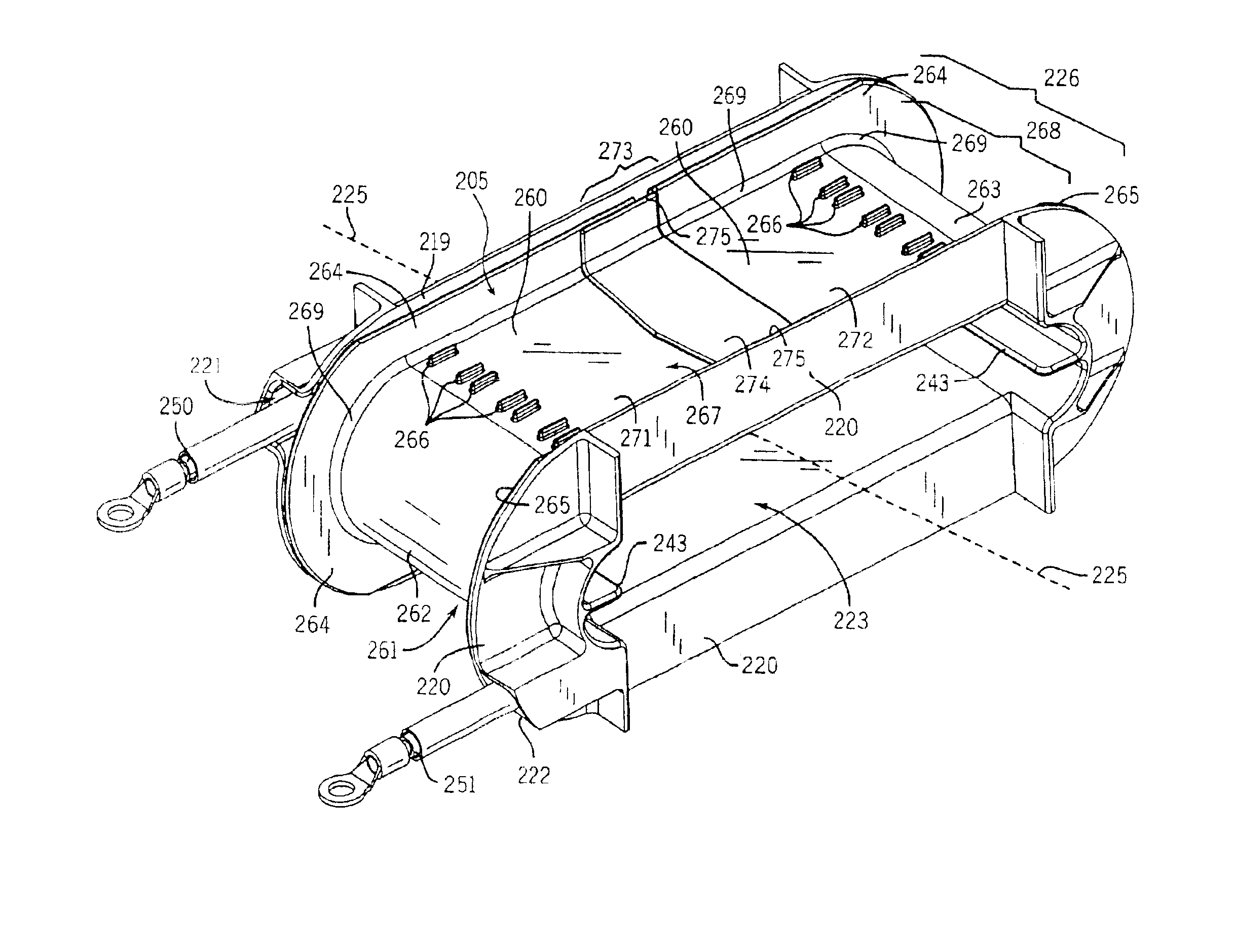
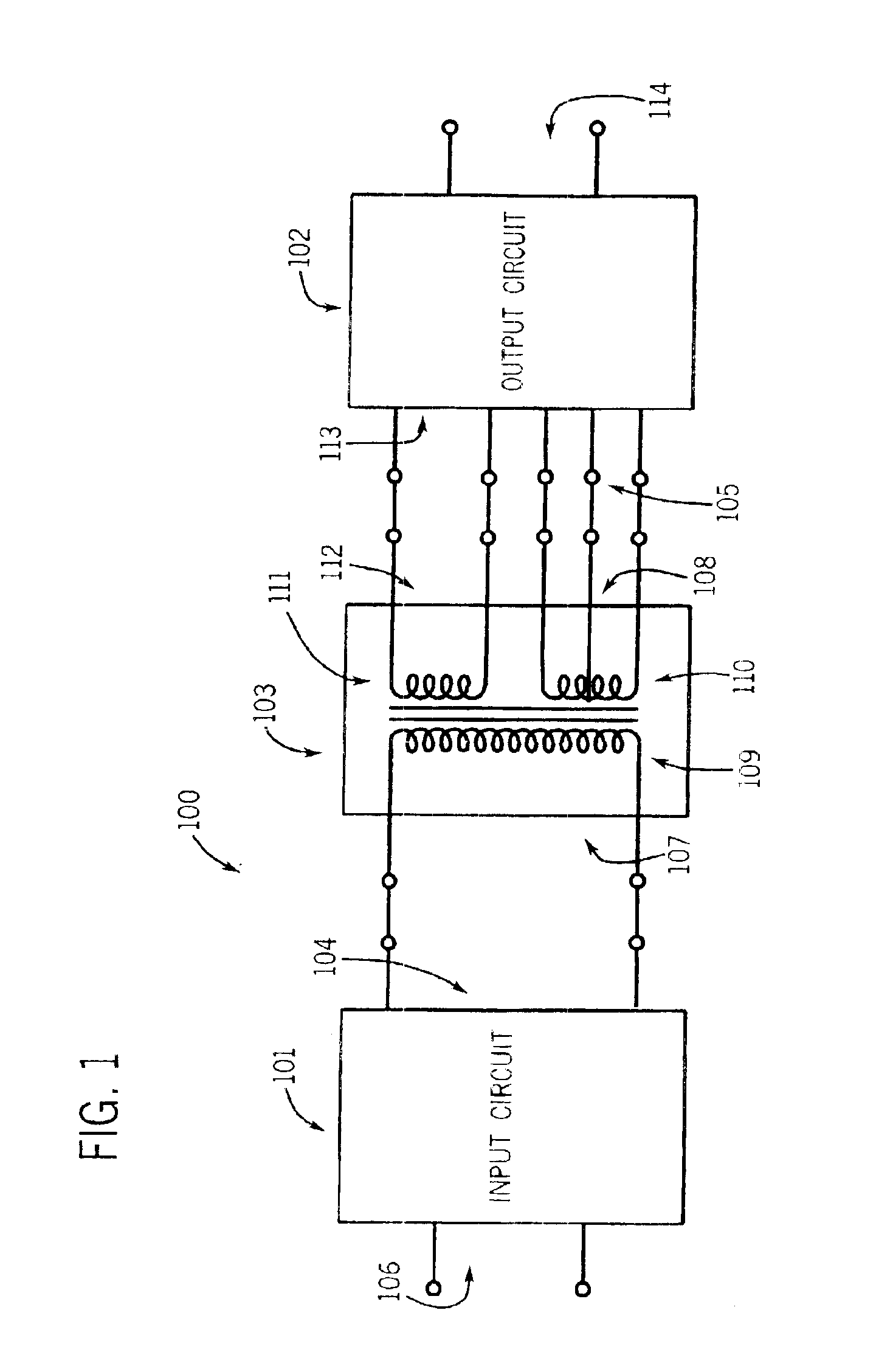
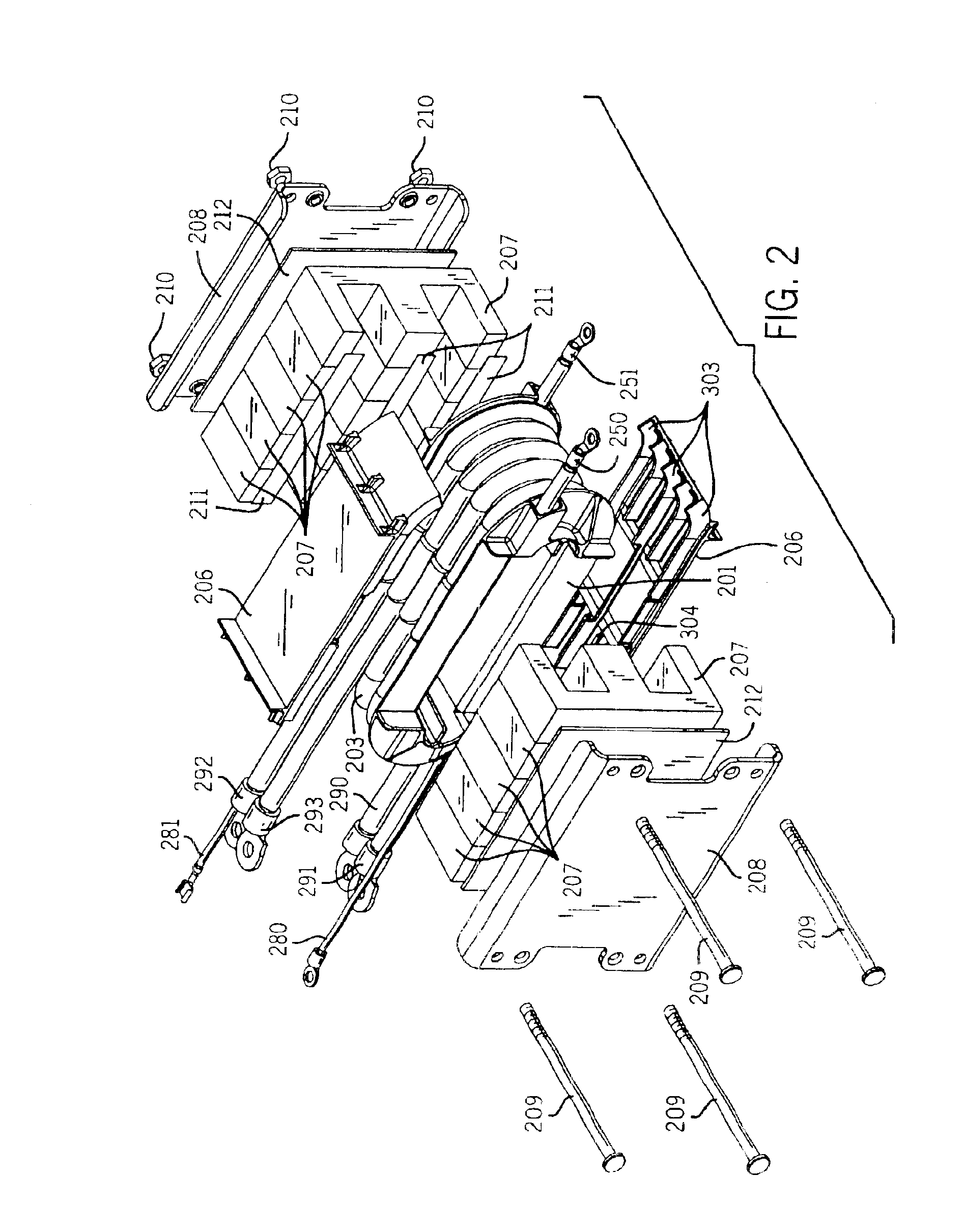
Generally, the present invention involves an electrical transformer for use in a welding power supply. Although discussed herein with reference to its use in a welding power supply, the present invention can also be used with other types of power supplies including plasma cutters and induction heaters. The term...


PUM


Abstract

A welding-type power supply transformer including a bobbin, a first coil and a second coil is disclosed. The first coil is wound around the bobbin. The second coil is magnetically coupled to the first coil.

Description

FIELD OF THE INVENTIONThe present invention relates generally to electrical transformers. More specifically, it relates to high voltage, high current electrical transformers for use in welding power supplies, plasma cutters and induction heaters.BACKGROUND OF THE INVENTIONHigh frequency transformers operating at high voltages and high currents are commonly used in welding power supplies. The output stage of a welding power supply, for example, may include an electrical transformer to transform the high bus voltage of the welding power supply into a high current welding output. Transformer primary coil voltages on the order of 465 volts at 20 to 100 Khz and secondary coil currents on the order of 400 amps are typical. Welding power supply transformer coils (e.g., primary and secondary coils) are made from large diameter wires (3-14 gauge wire is typical) in order to handle the temperatures generated by these large voltages and currents.Most of these transformers include a central bob...

Claims


Application Information

Patent Timeline
IPC IPC(8): H01F27/32H01F38/00H01F38/08
CPCH01F38/085H01F27/325
Inventor SIGL, DENNIS
Owner ILLINOIS TOOL WORKS INC
Why Eureka
Try Eureka