Serially-fed phased array antennas with dielectric phase shifters

a phase shifter and dielectric technology, applied in the field of phased array antennas, can solve the problems of phase shifting, ferroelectric phase shifters disclosed in those patents suffer from high conductor losses, bulk microstrip phase shifters suffer from the need for higher bias voltage, and achieve low loss tunable, wide frequency range, and low insertion loss

Inactive Publication Date: 2005-03-08
NXP USA INC
View PDF4 Cites 48 Cited by
  • Summary
  • Abstract
  • Description
  • Claims
  • Application Information

AI Technical Summary

Benefits of technology

[0012]Antennas constructed in accordance with this invention utilize low loss tunable film dielectric elements and can operate over a wide frequency range. The conductors forming the coplanar waveguide operate at room temperature. The devices herein are unique in design and exhibit low insertion loss even at frequencies in the above Ku band (12 to 18 GHz).

Problems solved by technology

Tuning of the permittivity of the substrate results in phase shifting when an RF signal passes through the phase shifter.
The ferroelectric phase shifters disclosed in those patents suffer high conductor losses, high modes, DC bias, and impedance matching problems at K (18 to 27 GHz) and Ka (27 to 40 GHz) bands.
Bulk microstrip phase shifters suffer from the need for higher bias voltage, complex fabrication processing and high cost.

Method used


Image

  • Serially-fed phased array antennas with dielectric phase shifters
  • Serially-fed phased array antennas with dielectric phase shifters
  • Serially-fed phased array antennas with dielectric phase shifters

Examples


Embodiment Construction

ed in an antenna constructed in accordance with the present invention;

[0020]FIG. 7 is a cross-sectional view of the phase shifter of FIG. 6, taken along line 7—7;

[0021]FIG. 8 is a top plan view of another phase shifter that can be used in an antenna constructed in accordance with the present invention;

[0022]FIG. 9 is a cross-sectional view of the phase shifter of FIG. 8, taken along line 9—9;

[0023]FIG. 10 is an isometric view of a phase shifter that can be used in an antenna constructed in accordance with the present invention; and

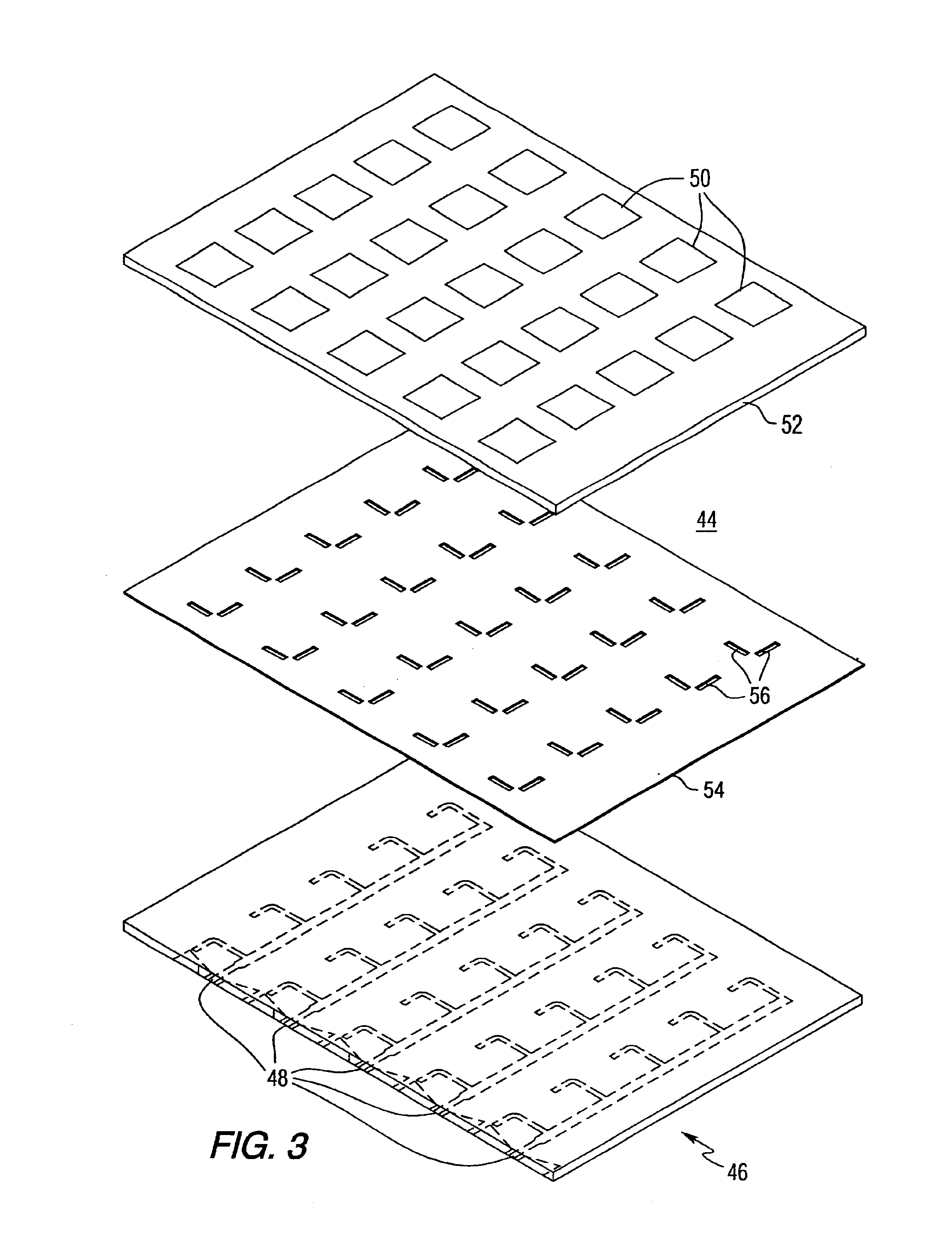
[0024]FIG. 11 is an exploded isometric view of an may of phase shifters that can be used in an antenna constructed in accordance with the present invention.

DETAILED DESCRIPTION OF THE INVENTION

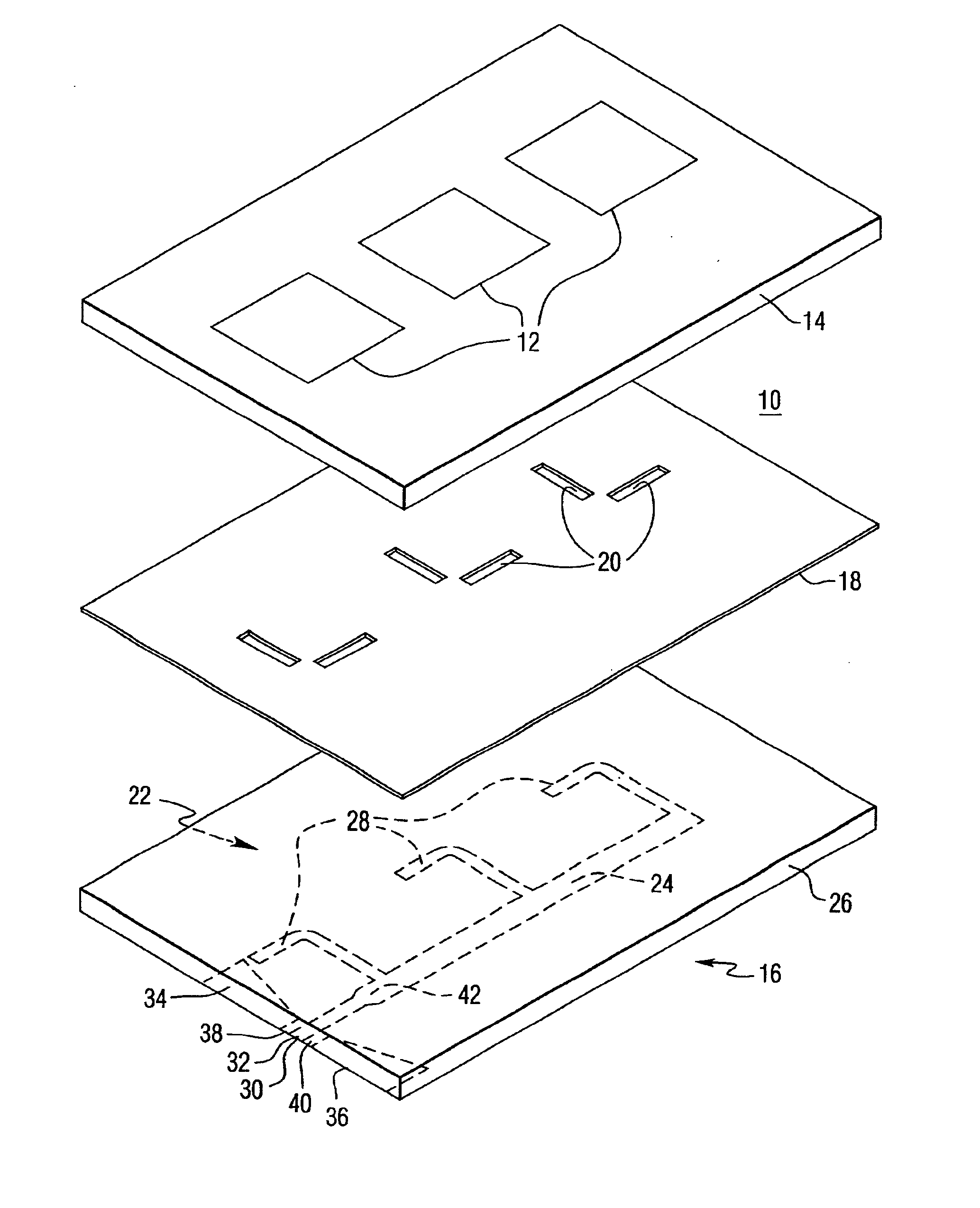
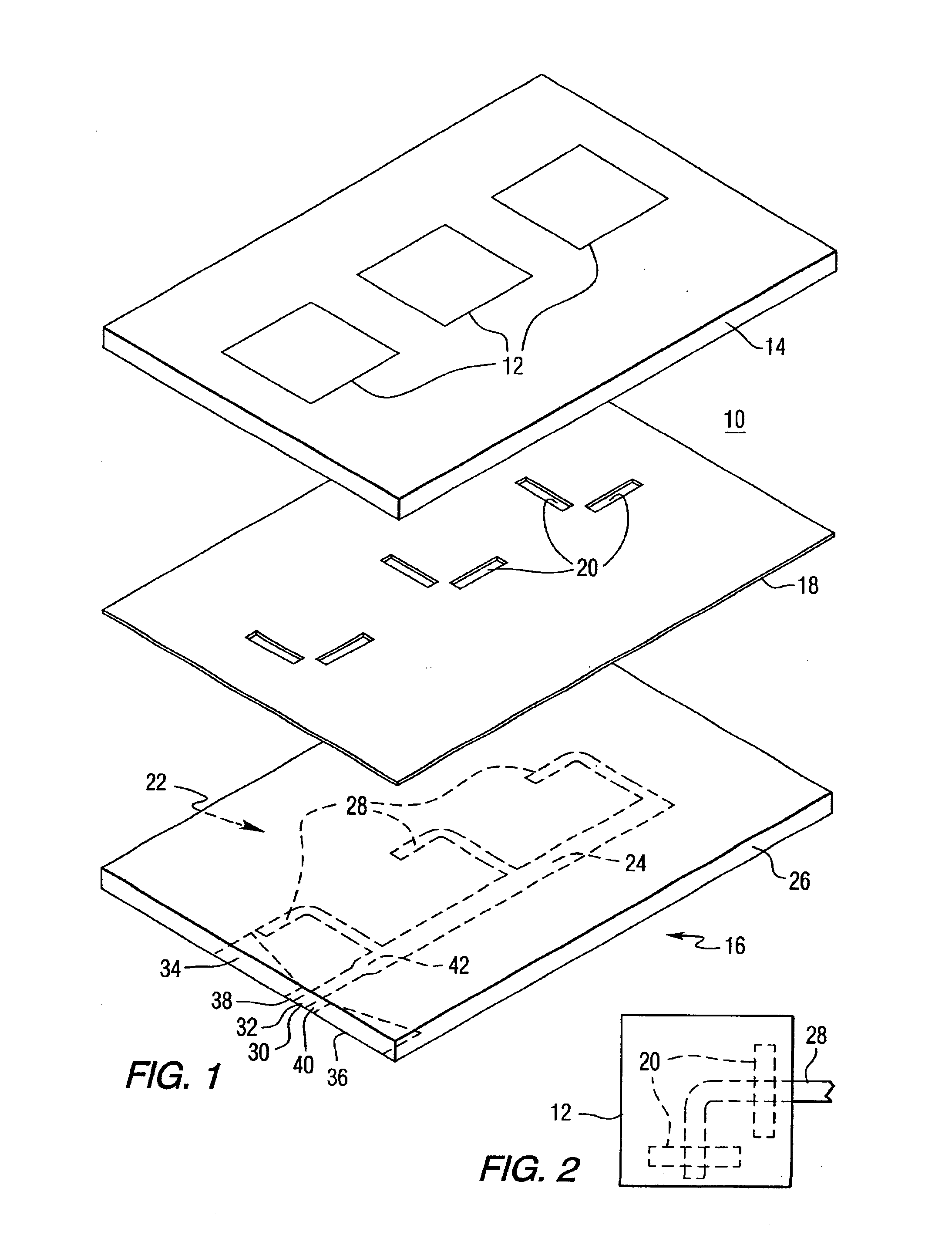
[0025]The preferred embodiment of the present invention is an electrically scanned phased array antenna including voltage-tuned coplanar waveguide (CPW) phase shifters and circularly polarized aperture-coupled microstrip patch elements. The CPW phase shifters include...


PUM


Abstract

A phased array antenna includes a plurality of radiating elements, a feed line assembly, a ground plane positioned between the plurality of radiating elements and the feed line assembly, with the ground plane having a plurality of openings positioned between the plurality of radiating elements and the feed line assembly, and a plurality of voltage tunable dielectric phase shifters coupled to the feed line assembly.

Description

CROSS REFERENCE TO RELATED PATENT APPLICATION[0002]This application is a continuation of U.S. patent application Ser. No. 09 / 660,719, filed Sep. 13, 2000, now U.S. Pat. No. 6,377,217 which claims the benefit of U.S. Provisional Patent Application Ser. No. 60 / 153,859, filed Sep. 14, 1999.FIELD OF INVENTION[0003]The present invention relates generally to phased array antennas, and more particularly to microstrip patch antennas having coplanar waveguide (CPW) voltage-tuned phase shifters.BACKGROUND OF INVENTION[0004]A phased array refers to an antenna having a large number of radiating elements that emit phased signals to form a radio beam. The radio signal can be electronically steered by the active manipulation of the relative phasing of the individual antenna elements. The electronic beam steering concept applies to antennas used with both a transmitter and a receiver. Electronically scanned phased array antennas are advantageous in comparison to their mechanical counterparts with r...

Claims


Application Information

Patent Timeline
Patent Type & Authority Patents(United States)
IPC IPC(8): H01Q3/30H01Q21/00H01Q21/06H01Q3/36H01P1/18H01P5/08H01Q13/08
CPCH01P1/181H01Q21/065H01Q21/0075H01Q3/36H01Q21/00
Inventor ZHU, YONGFEISENGUPTA, LOUISE C.KOZYREV, ANDREYZHANG, XUBAI
Owner NXP USA INC
Why Eureka
Try Eureka