

Stage apparatus, exposure apparatus and method for exposing substrate plate
a technology of exposure apparatus and substrate plate, which is applied in the direction of photomechanical equipment, instruments, printers, etc., can solve the problems of a large leakage, a serious inconvenience in the operating environment of the apparatus itself, and a gap of 1 micron or smaller
- Summary
- Abstract
- Description
- Claims
- Application Information
AI Technical Summary
Benefits of technology
Problems solved by technology
Method used
Image

Examples
first embodiment
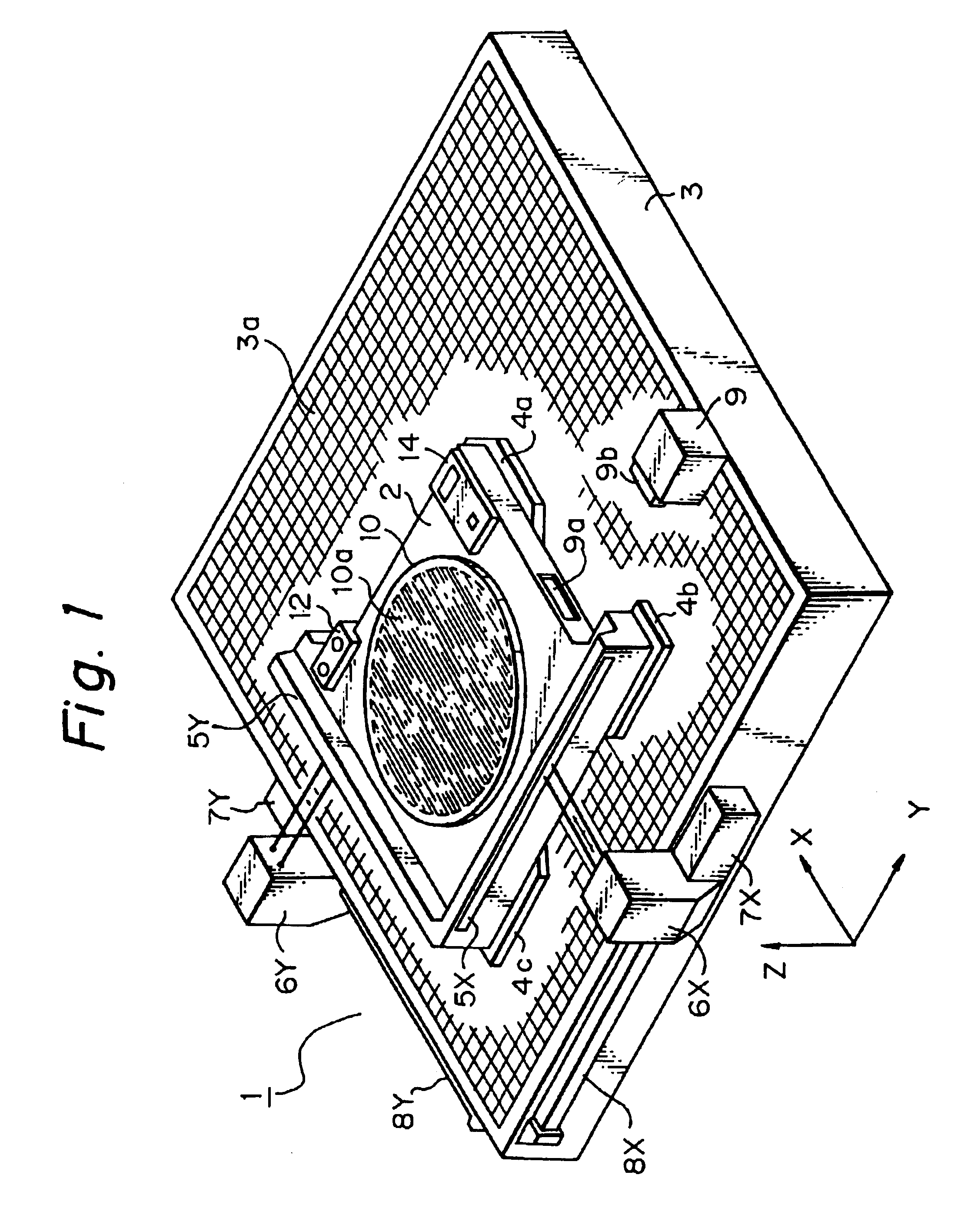
FIG. 1 is a perspective view showing an overall structure of a stage apparatus 1 in accordance with the present invention, in which a holder 10 with a semiconductor wafer as a processing substrate plate loaded thereon is provided at its loading surface with an electrode 10a for electrostatic adsorption of the semiconductor wafer thereon. The holder 10 is supported by a Z-directional minute motion mechanism and a leveling mechanism (both being referred to herein collectively as a Z / L fine motion mechanism), although not shown in the drawing. A movable main stage member 2 is supported so as to be movable two-dimensionally in the Y- and Y-directions along a defined flat plane 3a formed on a base table 3.
As specifically shown in FIG. 1, the stage apparatus 1 is of a guideless type having a full flat surface 3a supporting the own weight of the main stage member 2 as a Z-directional guide plane yet having no guide plane for movement in X- and Y-directions. At this end, the main stage memb...
second embodiment
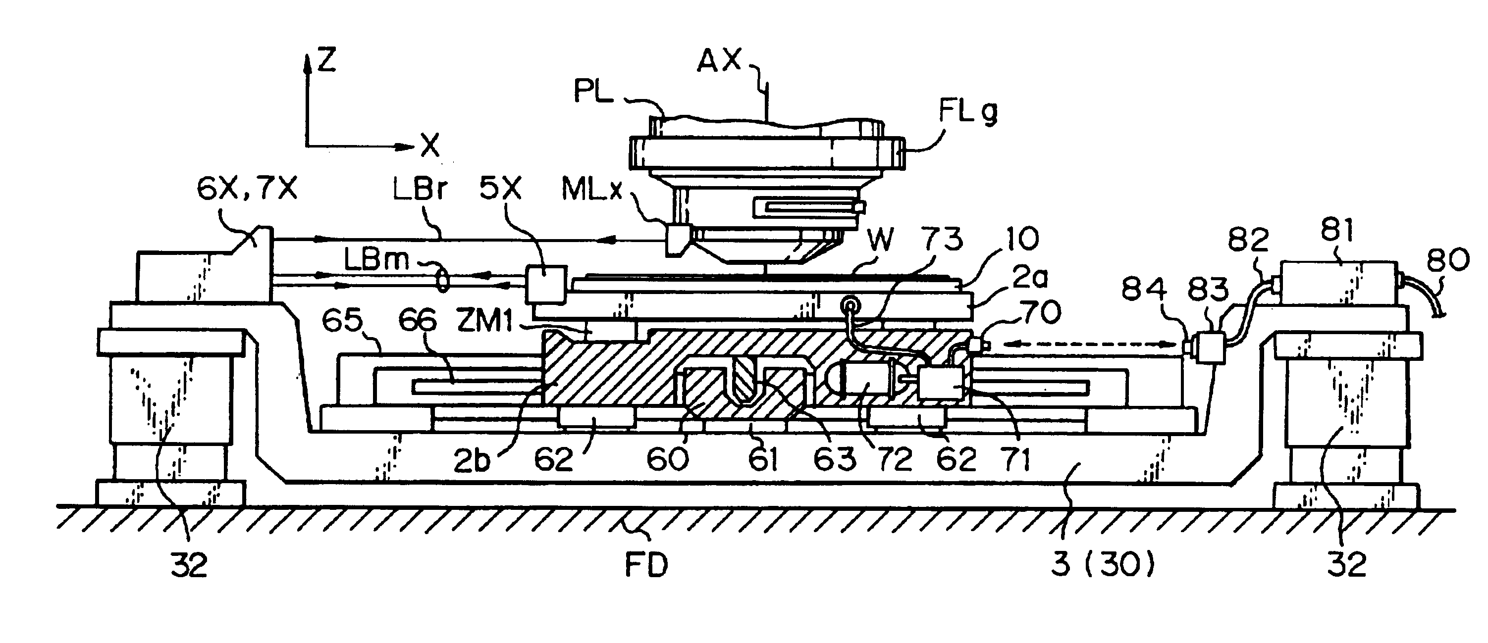
Now, a description will be made of the structure of the stage apparatus according to the present invention, with reference to FIGS. 5 and 6. The stage apparatus of FIG. 5 is structured with the presumption that it is loaded on the projection exposure apparatus as shown in FIG. 3. The structuring parts functioning in the same manner as the structure of the apparatus as shown in FIGS. 1 and 3 are provided with the identical reference numbers and symbols.
The stage apparatus as shown in FIG. 5 is not of such a guideless structure as illustrated by the apparatus as shown in FIG. 1 and in an air bearing guide system, which comprises three linearly drivable motors (linear motors) disposed in a H-letter shape, a linearly fixed guide member fixed to a table of the apparatus, a movable guide member disposed as to be movable along the fixed guide member and extending in a direction intersecting at a right angle with the fixed guide member, and a movable main stage member disposed so as to move...
third embodiment
Then, a description will be made of the structure of a stage apparatus according to the present invention, with reference to FIG. 13. FIG. 13 shows an embodiment of a variation in a fluid supply control system 81 on the apparatus column 30 side as shown in FIGS. 5 and 6. In this embodiment, the great features reside in the structures that, upon removal of the wafer W from the holder 10, the electromagnetic valve 71a on the main stage member 2 side is opened to communicate the receipt edge orifice 70 with open air and the wafer W is caused to float instantly by a minute length (several microns or smaller) positively from the surface of the holder 10.
In FIG. 13, the same structuring parts as shown in FIG. 6 are provided with the identical reference numerals and symbols, which include an electromagnetic valve 81a, a drive part 81b, a signal SV1, a tube 82, a fixing member 83, a feed edge orifice 84 and a bellows 85. The original vacuum pressure from the source for supplying the pressur...
PUM
 Abstract
Description
Claims
Application Information