
Device for x-ray lithography

a technology of x-ray lithography and x-ray light, which is applied in the direction of instruments, photomechanical equipment, and handling using diaphragms/collimeters, etc., can solve the problems of falling on the mask, destroying the mask further, and not being able to meet the radiation intensity uniformly

Inactive Publication Date: 2005-03-08
KUMAKHOV MURADIN ABUBEKIROVICH
View PDF11 Cites 3 Cited by
  • Summary
  • Abstract
  • Description
  • Claims
  • Application Information

AI Technical Summary

Problems solved by technology

Non-uniform radiation intensity decreasing toward a periphery of the output face of a lens, falling on a mask, is a disadvantage of the described prior art devices.
The second mentioned variant of placing an absorbing filter is obviously poor, as according to this variant a radiation of extra intensity exposures on the central part of the mask, being an expensive precise unit, will result in destruction of the mask Further, the influence of actual out-of-parallelism of emergent radiation of a half lens appears in this variant to a greater extent.
Placing the filter after the mask inevitably increases this distance.
However according to this variant as well a radiation, which extra intensity should be attenuated, passes through another expensive unit of the device, an X-ray half lens, what results in its aging.
In spite of using special high-precise devices for this purpose, it is impossible to avoid errors, caused by errors in conjugation of neighboring zones under exposure.

Method used


Image

  • Device for x-ray lithography
  • Device for x-ray lithography

Examples


Embodiment Construction

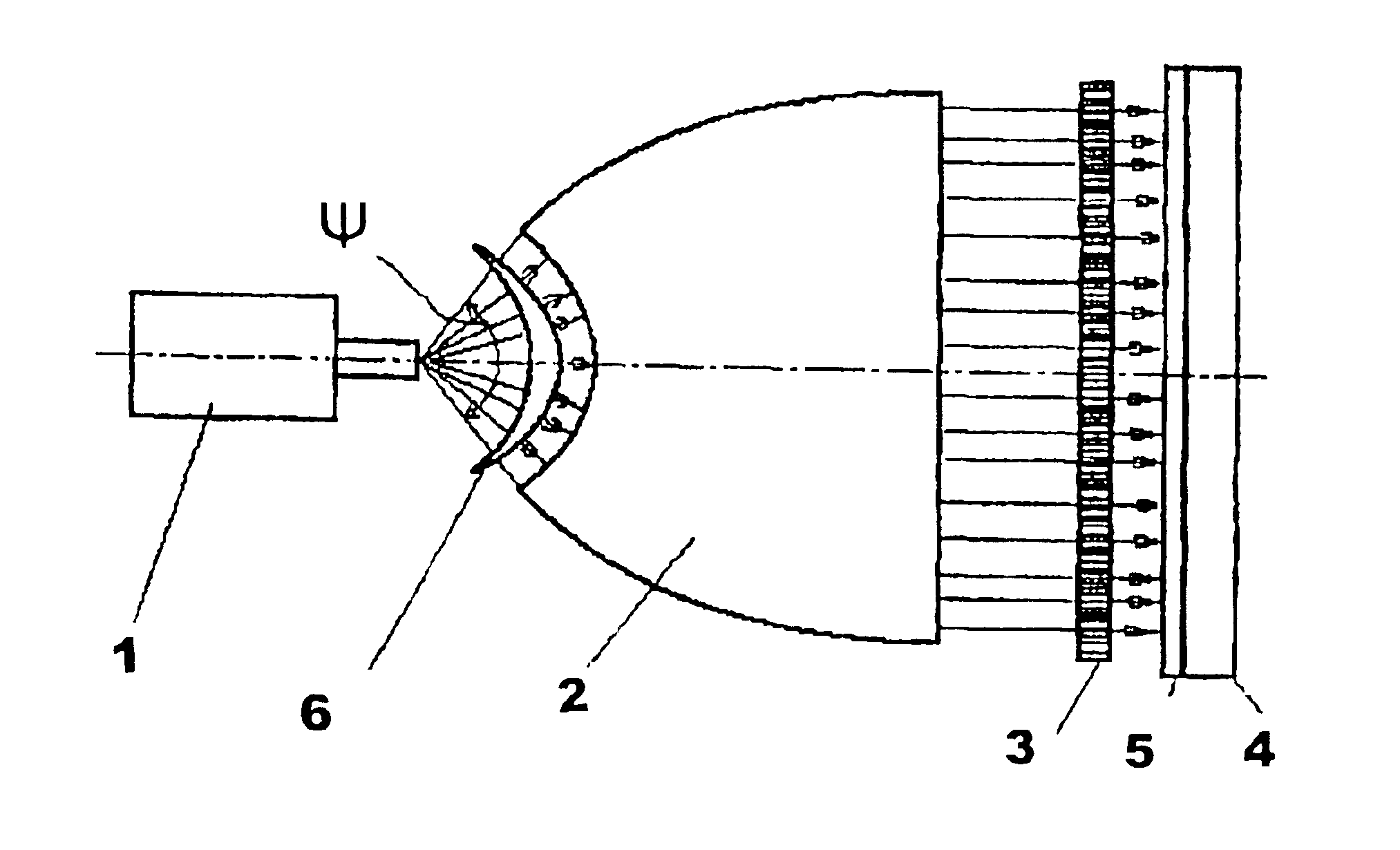
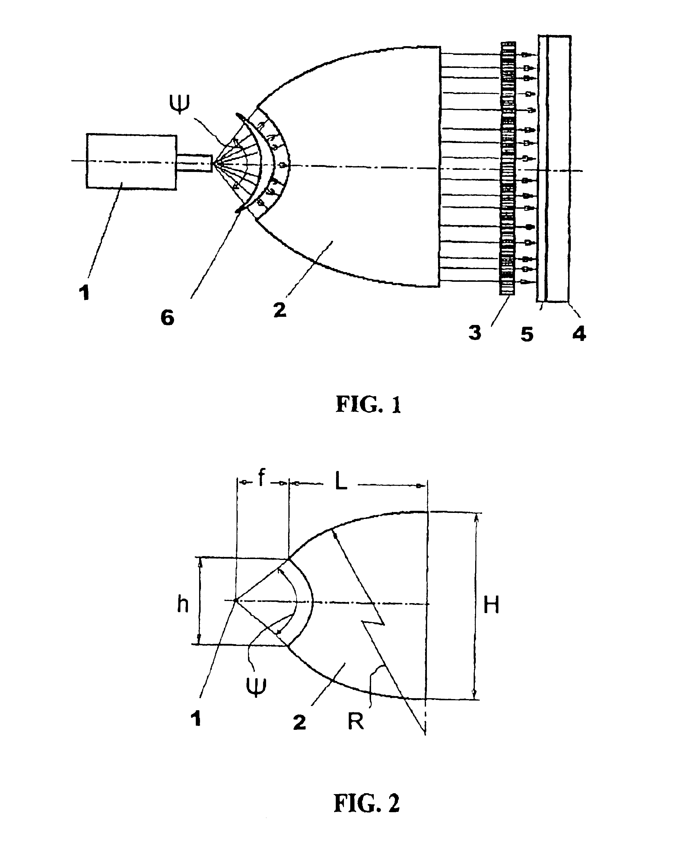
An X-ray lithography device includes a source of divergent soft X-rays 1, wherein an output aperture is placed in the focus of a half lens 2. A mask 3 is located on the side of an output face of half lens 2. A plane of mask 3 is parallel to the output face of half lens 2, i.e. the mask 3 is perpendicular to a longitudinal axis of the half lens 2 and to an axial line of an emergent quasi-parallel radiation beam formed by the half lens 2.

A substrate 4 is placed with a layer of resist 5 applied on it and is located after the mask 3. The substrate 4 should be located so that a plane of resist 5 is parallel to a plane of mask 3, and it is spaced from the mask 3 at a minimum distance.

An absorbing filter 6 is placed between X-ray source 1 and the input face of half lens 2. The absorbing filter 6 represents a product made of material, absorbing an X-rays, as an axi-symmetric body, being relative to an axis combined with a longitudinal axis of a half lens. A thickness of the absorbing filter...


PUM

PropertyMeasurementUnit
radiation energyaaaaaaaaaa
atomic numberaaaaaaaaaa
capture angleaaaaaaaaaa

Abstract

A lithography device including a soft X-ray source 1 transforming to a quasi-parallel radiation apparatus for placing a mask 3 and a plate-substrate 4 coated with a resist 5, and an absorbing filter 6 for smoothing of intensity decreasing as from the center to the periphery of a beam. The filter 6 is placed between the source 1 and the input face of the half-lens 2. The half-lens has an enlarged capture angle. This angle is chosen depending on radiation energy (0.6-6 keV) of the source 1. As a result, there is an opportunity to increase the size of the plate-substrate.

Description

The invention relates to means for X-ray contact lithography used in microelectronics, namely for lithography devices, which use X-ray lenses for forming an X-ray quasi-parallel beam.BACKGROUND OF THE INVENTIONThe first information about such devices relates to the end of the 1980's . Some works, describing the application of X-ray lenses in lithography devices, one can find in: “Book of Abstracts. 3rd All-Union Conference on Relativistic Particles Radiation in Crystals. May 25-30, 1988”. (Nalchik, 1988) [1]. If a divergent radiation source is used these devices comprise a lens, transforming the radiation to a quasi-parallel one directed through the mask on the resist, applied on the substrate. The lens comprises a set of channels for directing radiation curved along a barrel-shaped generatrix. An effect of multiple total external reflections from the walls of the channels is used when a radiation is transmitted. As a whole, a lens for a divergent radiation changing to a quasi-paral...

Claims


Application Information

Patent Timeline
Patent Type & Authority Patents(United States)
IPC IPC(8): G03F7/20G21K1/00G21K1/06G21K5/00G03B42/02G21K5/02H01L21/027
CPCB82Y10/00G03F7/70166G21K1/06G03F7/702G03F7/7035G03F7/70191G21K5/00
Inventor KUMAKHOV, MURADIN ABUBEKIROVICH
Owner KUMAKHOV MURADIN ABUBEKIROVICH
Learn More