Eureka AIR delivers breakthrough ideas for toughest innovation challenges, trusted by R&D personnel around the world.

Method and apparatus for providing distributed control of a home automation system

a technology for home automation and distributed control, applied in computer control, data switching networks, program control, etc., can solve the problems of single point of failure of central controller, scene no longer being triggered, and entire home automation system being rendered unusable, so as to eliminate the single point of failure

Inactive Publication Date: 2005-03-08
MICROSOFT TECH LICENSING LLC
View PDF9 Cites 84 Cited by
  • Summary
  • Abstract
  • Description
  • Claims
  • Application Information

AI Technical Summary

Benefits of technology

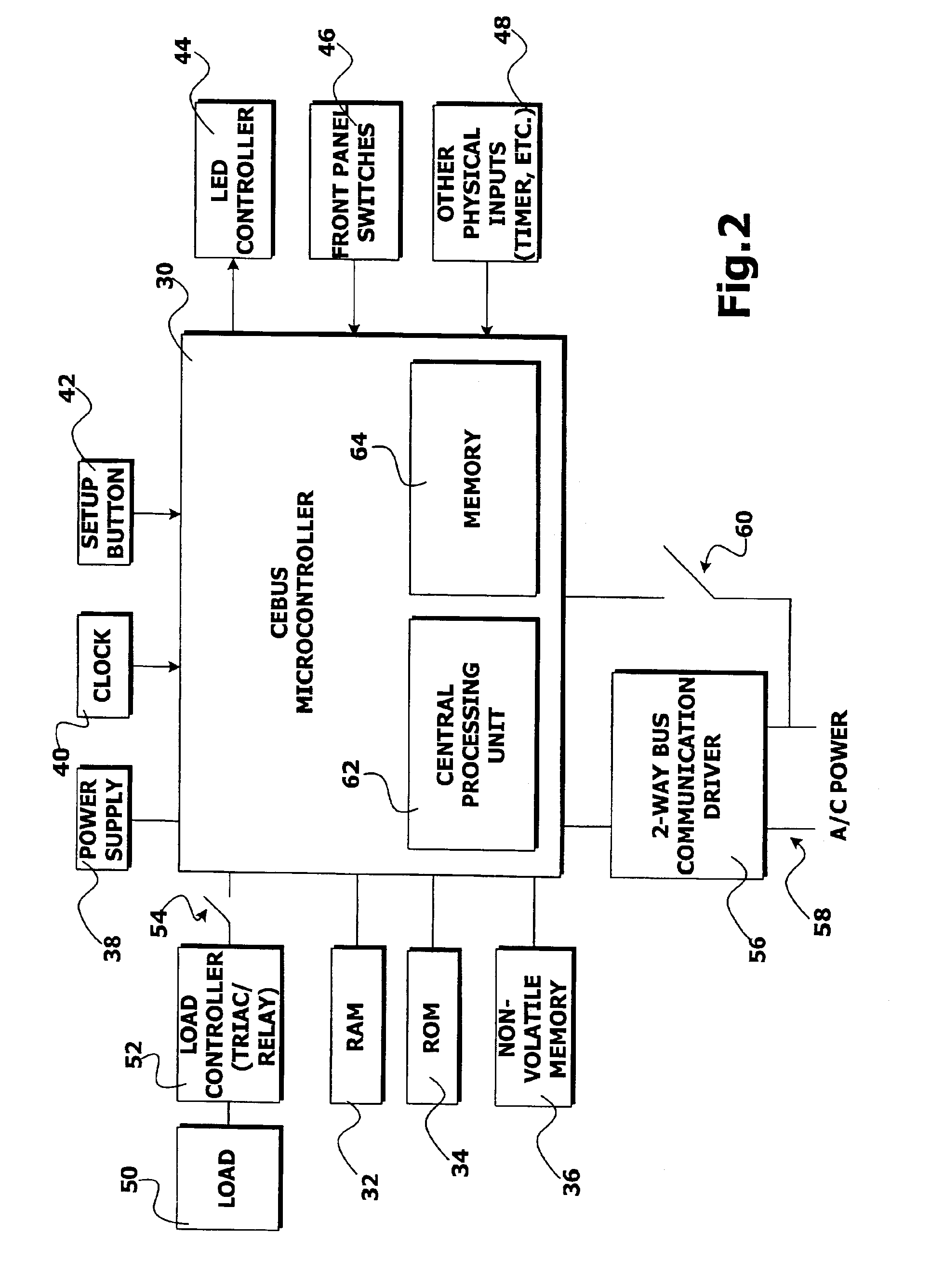
The present invention provides a method and system for providing distributed control of a home automation system. According to an embodiment of the present invention, a microcontroller is embedded into each device within a home automation system along with logic for distributing control of the system to all of the participating devices. By embedding control logic within each device, control of the system is distributed, thereby eliminating the single point of failure found in previous home automation systems. According to the present invention, any device in the system may fail and the other devices will continue operating normally.
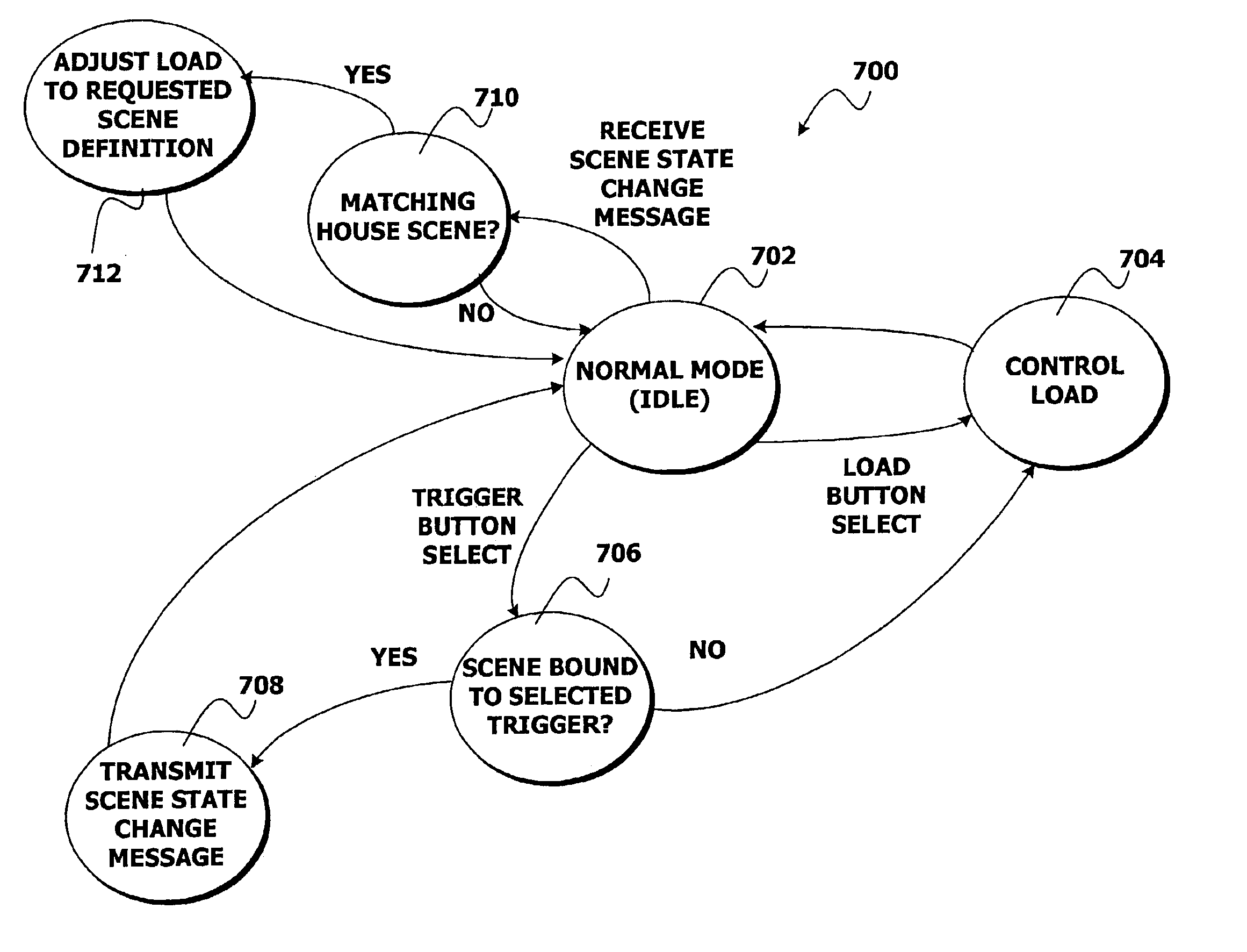
An aspect of the invention also provides for reduced network traffic for launching a scene as compared to prior art solutions. In particular, according to an embodiment of the present invention, only a single trigger message must be sent to devices participating in the scene in order to launch the scene. No other message traffic is necessary. Moreover, each device maintains its own scene definition for each scene describing the state of the device for the scene. Therefore, the trigger message only needs to identify the scene to the device in order for the scene to be launched. Such a message allows for scene control to be distributed throughout the home automation system, and also reduces the delay found in previous home automation systems between the time a trigger event is received and when the last scene member is activated.
According to another embodiment of the present invention, a simple programming interface is provided for programming scenes in a distributed control environment. According to this embodiment of the present invention, an indication is received at one of the devices in the home automation system that the devices should be placed into a scene programming mode. In response to the indication, a message is broadcast to each device, thereby placing all devices in the scene programming mode.
According to another embodiment of the present invention, a simple programming interface is provided for programming a multi-way lighting context in a distributed control environment. Through a multi-way lighting context, any device in a multi-way lighting group of devices can directly control all of the devices in that group. According to this embodiment of the present invention, an indication is received at one of the devices in the home automation system that the devices should be placed into a multi-way programming mode. In response to the indication, a message is broadcast to each device, thereby placing all devices in the multi-way programming mode.

Problems solved by technology

Because all messages go through the central controller, the central controller creates a single point of failure.
If the central controller fails, then scenes can no longer be triggered because the controller can no longer send the necessary messages to the scene member devices to produce the scenes.
In effect, if the central controller fails, the entire home automation system is rendered unusable.
This single point of failure is highly undesirable to users of such systems.
Additionally, the use of a central controller creates a heavy load of network traffic.
For a scene with a large number of devices, this also causes a time delay time between the start of the scene when the first device gets its message until the last device gets its message.
Such heavy network traffic and delay in triggering scene member devices is also undesirable to users of home automation systems.

Method used


Image

  • Method and apparatus for providing distributed control of a home automation system
  • Method and apparatus for providing distributed control of a home automation system
  • Method and apparatus for providing distributed control of a home automation system

Examples


Embodiment Construction

The present invention is directed to a method and apparatus for providing distributed control of a home automation system. According to an embodiment of the present invention, a device is provided for use in a home automation system that includes control logic for providing distributed control and for providing a simple programming interface to the device. When multiple such devices are utilized throughout a home automation system, control of the system is distributed among the devices. Moreover, a consistent user interface for programming the home automation system is provided across the system. Once a user of the home automation system understands how to program one device, they can similarly program all other devices in the system.

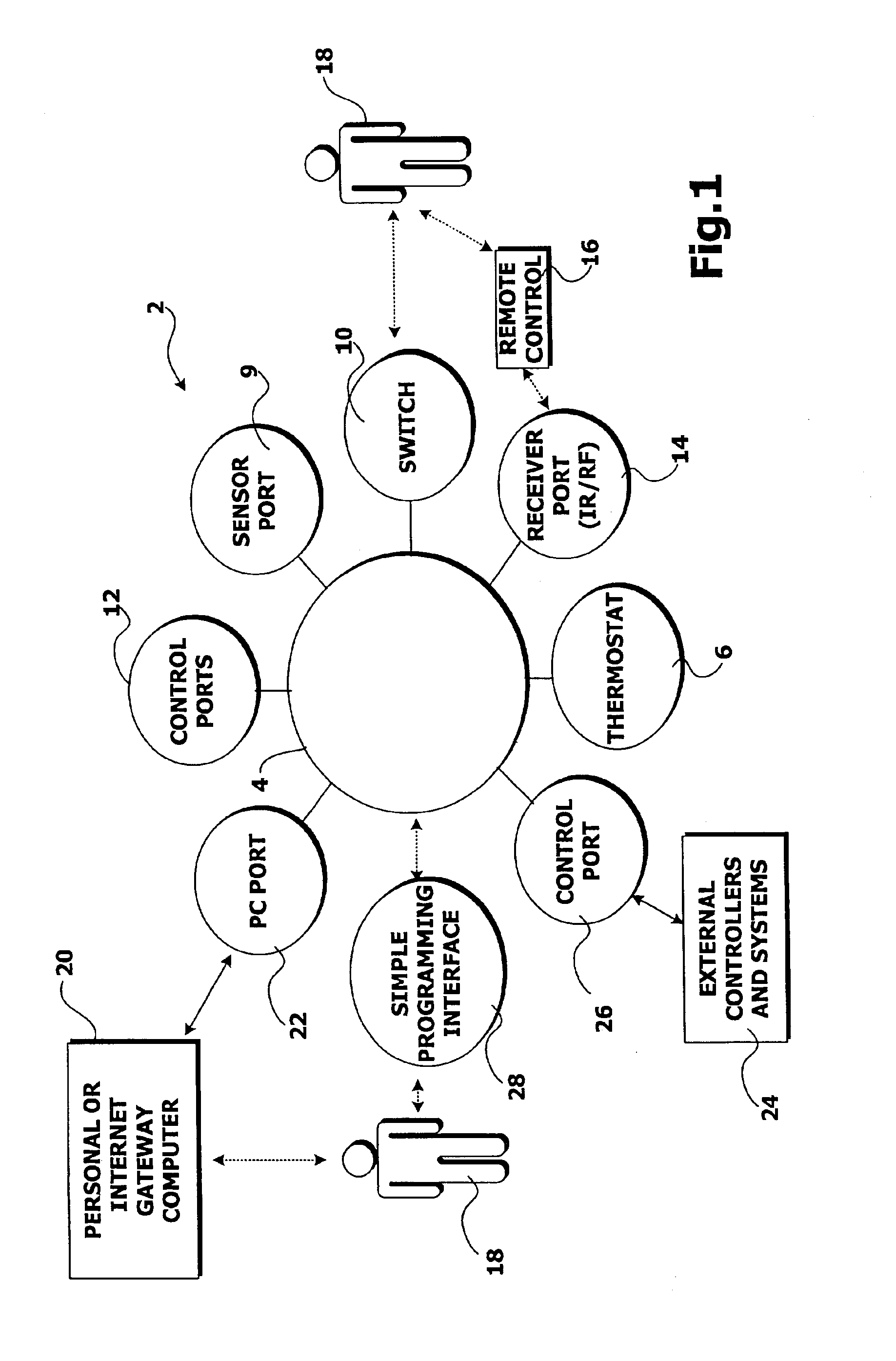
Referring now to the figures, in which like numerals represent like elements, an actual embodiment of the present invention will be described. FIG. 1 provides an overview of an illustrative home automation system 2 in which aspects of the present invent...


PUM


Abstract

A method and apparatus for providing distributed control of a home automation system is provided. Each device participating in a home automation system is equipped with control logic for providing distributed control. Through the control logic, each device maintains scene definitions describing the state of the device for each scene in which it participates. When any device in the system receives a request to launch a scene, such as a button press on one of the devices, the device broadcasts a scene state change message to all devices within the home automation system. The scene state change message identifies to each device a particular scene that should be launched. Each device in the system receives the message and determines whether the device is a participant in the scene. If the device is a participant in the scene, the device adjusts its state according to a scene definition stored in the device associated with the scene. The device may adjust a controlled electrical load, such as a light, according to the scene definition by turning the load on, off, or setting the load to some intermediate value.

Description

FIELD OF THE INVENTIONThe present invention relates to the field of home automation systems and, more particularly, to a method and apparatus for providing distributed control of a home automation system and simple connectivity of networked products.BACKGROUND OF THE INVENTIONHome automation systems are used to control the behavior of an environment such as a home or office building. Currently, home automation systems require a central controller to create and launch “scenes,” also called house scenes, involving multiple controlled devices. A scene is a collection of devices, such as lighting, heating and air conditioning, landscape sprinklers, window treatments, audio / visual equipment, water heaters, humidifiers, etc., set in a specific state. For example, through the use of a central controller, a user could create a scene where certain lights are set at specified levels, where the thermostat is set at a specified level, and where a stereo unit is activated and set to a particular...

Claims


Application Information

Patent Timeline
IPC IPC(8): H04L12/28H01H1/36H01H15/00
CPCH01H15/005H04L12/2803H04L12/2814H04L12/282H01H1/365Y04S20/228H04L12/2823H04L12/2827H04L2012/2849H04L2012/285Y02B70/325H04L12/2821Y02B70/30Y04S20/20
Inventor GONZALES, GREGSWENSEN, ARLEE C.BAKER, BRIAN D.
Owner MICROSOFT TECH LICENSING LLC
Why Eureka
Eureka Blog
Learn More