
Communication network for an automobile

a technology for communication networks and automobiles, applied in data switching networks, instruments, electric devices, etc., can solve problems such as cable routing difficulties, no way for a node to determine the physical node topology, and difficult for a technician to diagnose and locate the malfunctioning piece of equipment, so as to facilitate equipment installation and anomaly diagnostics

Inactive Publication Date: 2005-03-08
VISTEON GLOBAL TECH INC
View PDF20 Cites 67 Cited by
  • Summary
  • Abstract
  • Description
  • Claims
  • Application Information

AI Technical Summary

Benefits of technology

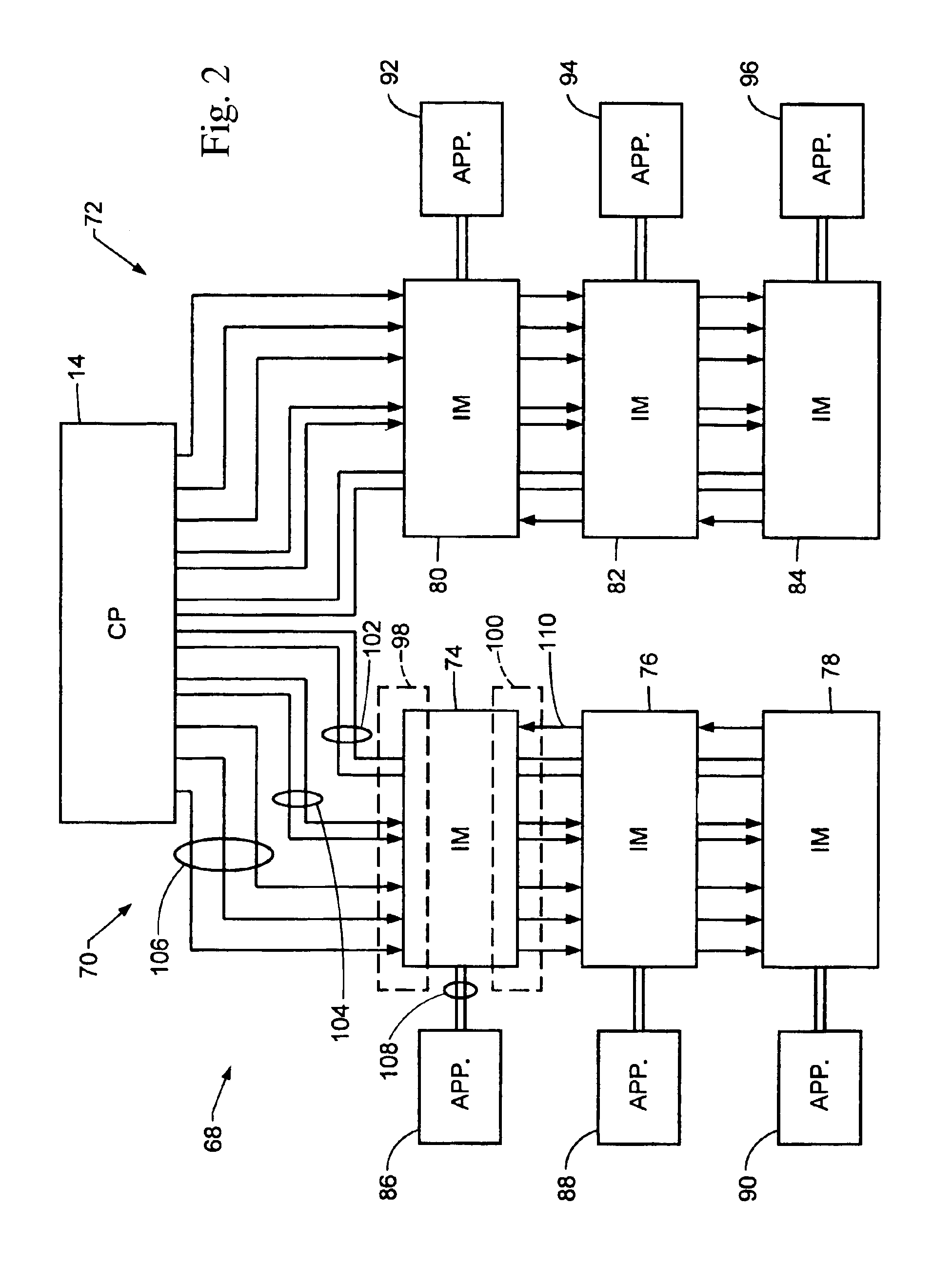
The present invention is a system that allows for the unique identification and isolation of nodes in a network, such as a CAN bus, without the need for additional hardware or human intervention. The system also allows for the addition of new appliances with their own characteristics by creating a new interface module tailored to the device. The system can verify that its configuration matches the control tables in the system and correct discrepancies that are found. The system also includes a configuration utility that generates the control tables for the system, combining the hardware layout with customer preferences to generate a control strategy for each node. Overall, the invention provides a consistent set of messages for appliances of each type, regardless of the make / model of the appliance or the individual interface needs of the appliance.

Problems solved by technology

In most local area networks, nodes have IDs that can identify the physical nodes (e.g., their addresses), however there is no way for a node to determine the physical node topology.
When a node cannot determine the physical node topology, in the event of an anomaly it is extremely difficult for a technician to diagnose and locate the malfunctioning piece of equipment.
While most local networks have a forced topology of a star or a bus, either of these network topologies can cause cable routing difficulties.
Employing a network with a bus topology necessitates routing a single CAN network cable throughout the vehicle, resulting in the difficult task of optimizing the route of one cable throughout the entire automobile.
Moreover, employing a single CAN network cable increases both the possibility of a single point failure of the network and the impact of such a failure should one occur.
However, as disclosed by Wright, the entire control system will fail should the IDB fail because no piece of equipment will be controllable by the realtime microcontroller.
However, similar to Wright, if the primary bus fails then the entire automobile information system fails.

Method used


Image

  • Communication network for an automobile
  • Communication network for an automobile
  • Communication network for an automobile

Examples


Embodiment Construction

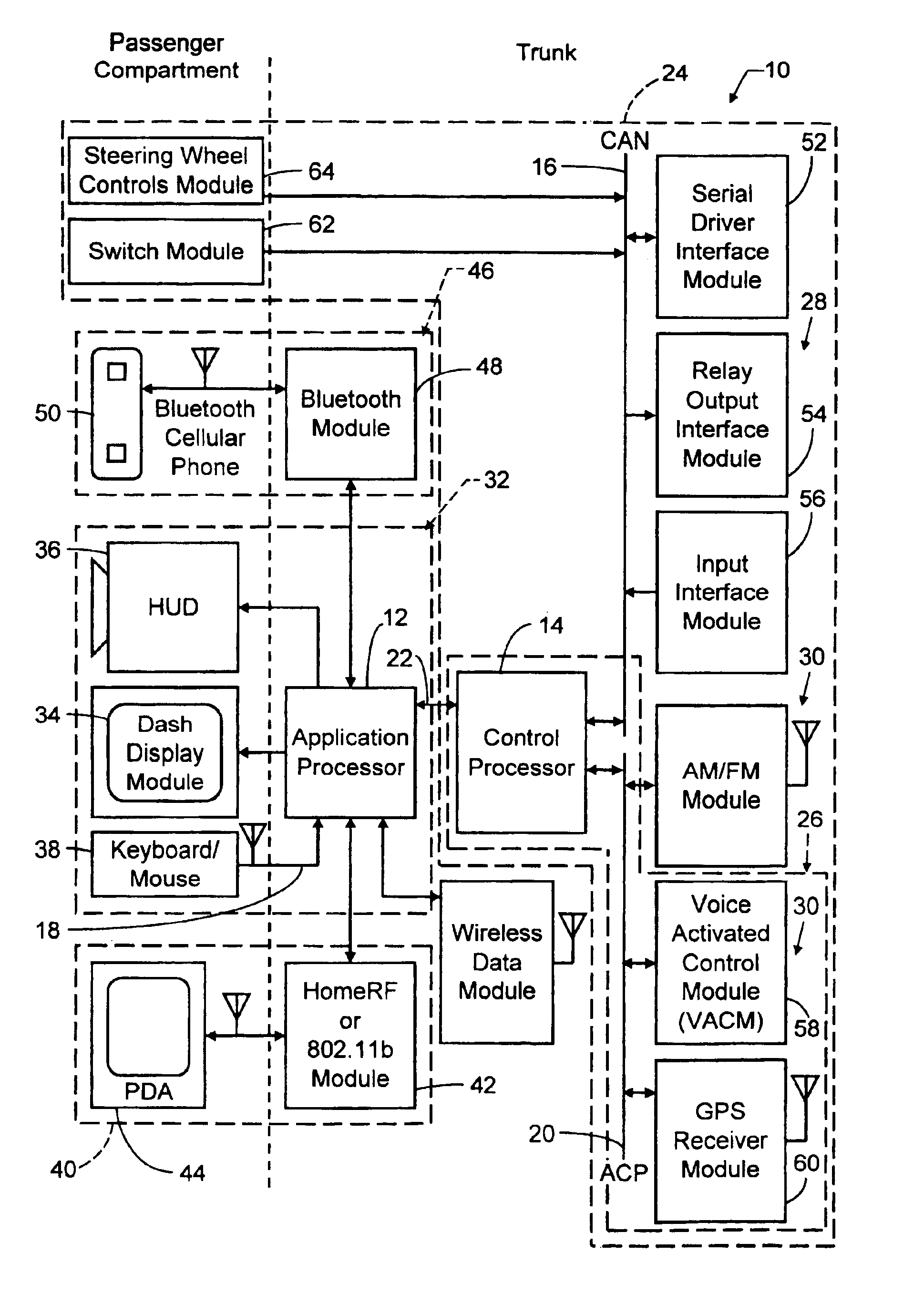
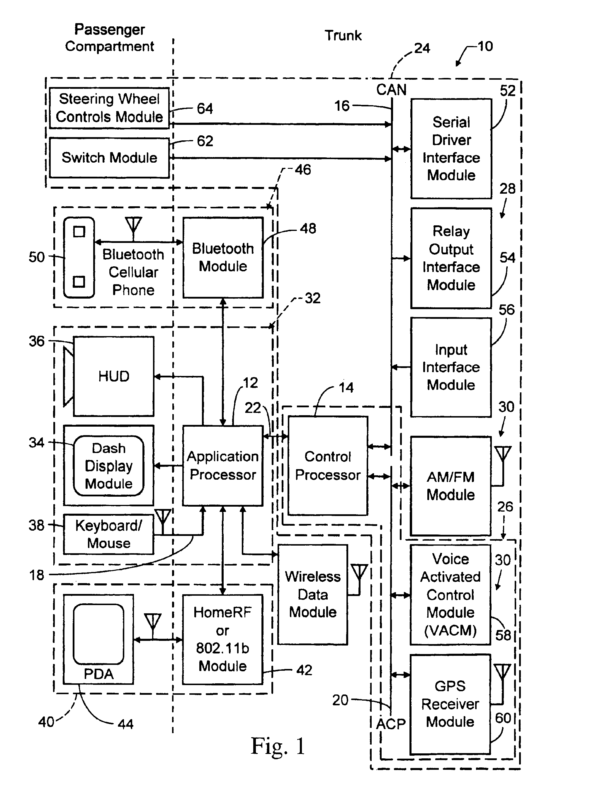
With reference to FIG. 1, a system 10 for controlling a plurality of electronic devices in an automobile is illustrated, in accordance with the present invention. The system 10 will be described with reference to an emergency vehicle, such as a police vehicle, and with reference to police equipment. However, it is contemplated that the communication network of the present invention may be utilized in any environment and with any equipment.

In an embodiment of the present invention an architecture of system 10 referred to as “little boxes” architecture is provided. This architecture is a distributed architecture. Each “box” in the architecture performs a specific task (e.g., a display driver or voice recognition). For example, two of the boxes are processors: a Windows Application Processor (AP) 12 and an embedded Control Processor (CP) 14. Other boxes represent all of the attached equipment or appliances. The boxes or appliances are connected to the AP and CP via a Controller Area Ne...


PUM


Abstract

A “segmented” CAN bus is provided that extends the cabling scheme of a CAN network to permit isolation of individual nodes of identical type when needed and the ability for a host to determine the network topology. In addition, the CAN bus cabling scheme automatically assigns unique addresses to nodes and guarantees that the network will always be properly terminated. This eliminates the need for jumpers, DIP switches, pre-installation programming, or other hardware requiring human intervention to uniquely identify the nodes on the network. Furthermore, because the physical node topology is determinable, equipment installation and anomaly diagnostics are facilitated.

Description

TECHNICAL FIELDThe present invention relates to systems and methods for communicating control and data signals to and from various appliances in an automobile.BACKGROUNDConventional embedded systems are designed to control a wide variety of equipment, where the customer (not the system vendor) has the responsibility of choosing the equipment, connecting the equipment to the system, and making the system work. When such a system is delivered to large numbers of end users (many thousands) it becomes necessary for the system to be easily configured and to be error-proofed against mistakes made by the customer. Complicating the problem, the variety of equipment in the field is large and the vendor of each piece of equipment determines its properties and its interfaces. A solution must accommodate such variability, including differences in the electrical interfaces and the higher-level protocols, while still providing a system that is easily configured by the customer.In most local area ...

Claims


Application Information

Patent Timeline
Patent Type & Authority Patents(United States)
IPC IPC(8): H04L12/407H04L12/413H04L12/56H04L29/12
CPCH04L12/40006H04L12/403H04L12/4135H04L61/00H04L29/12009H04L2012/40273H04L2012/40215
Inventor BRAY, THOMAS J.BERNEIS, PAUL ALLENMELNYK, BORYS JOSEPHMATSON, JEFF
Owner VISTEON GLOBAL TECH INC
Learn More