Method and system for logic verification using mirror interface

a technology of logic verification and mirror interface, applied in the direction of testing circuits, cad circuit design, instruments, etc., can solve the problems of complex verification of socs, requiring standardized models, and requiring much more functionality

a technology of logic verification and mirror interface, applied in the direction of testing circuits, cad circuit design, instruments, etc., can solve the problems of complex verification of socs, requiring standardized models, and requiring much more functionality

US6865502B2Inactive Publication Date: 2005-03-08GLOBALFOUNDRIES INC

Image

  • Method and system for logic verification using mirror interface
  • Method and system for logic verification using mirror interface
  • Method and system for logic verification using mirror interface

Examples


Embodiment Construction

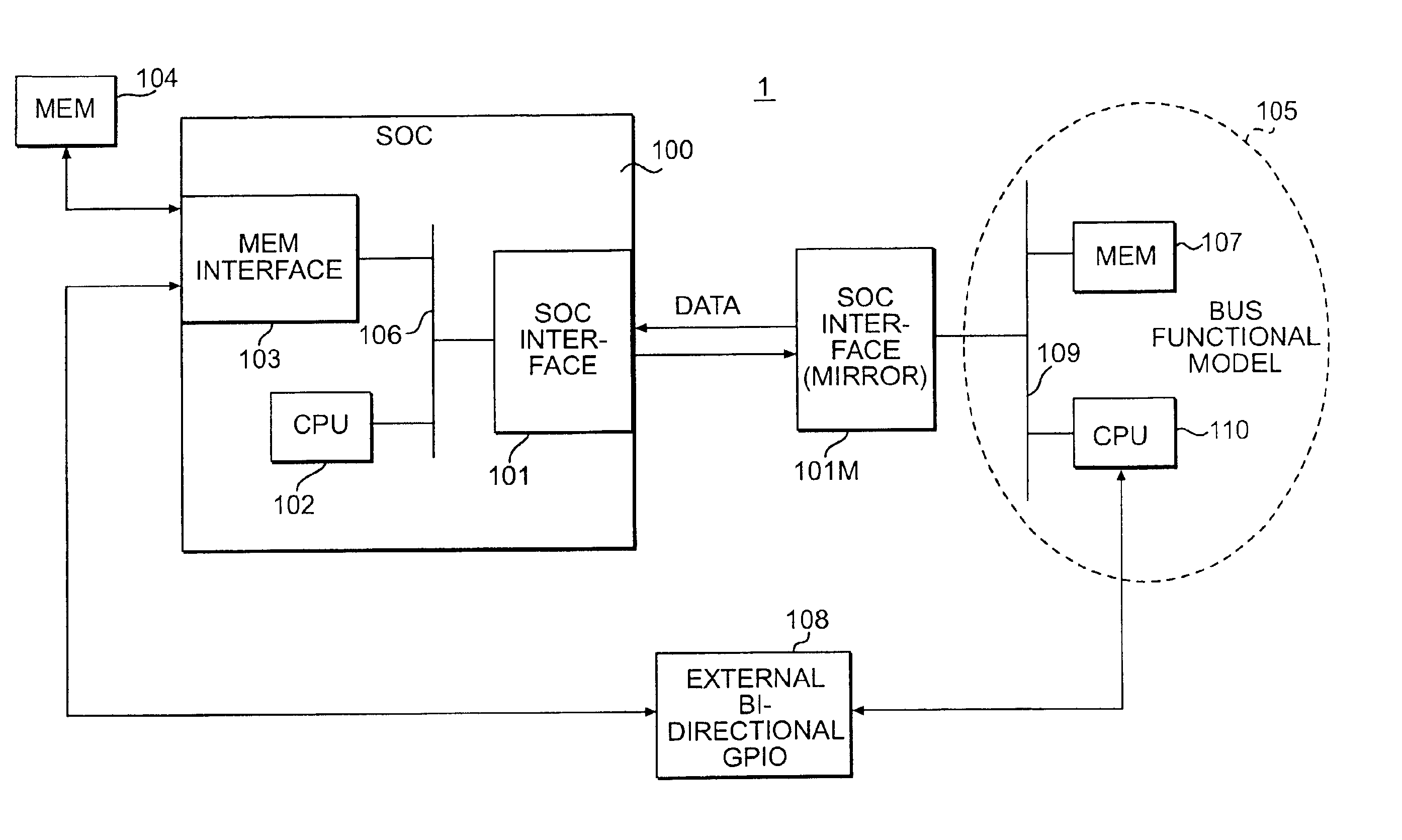
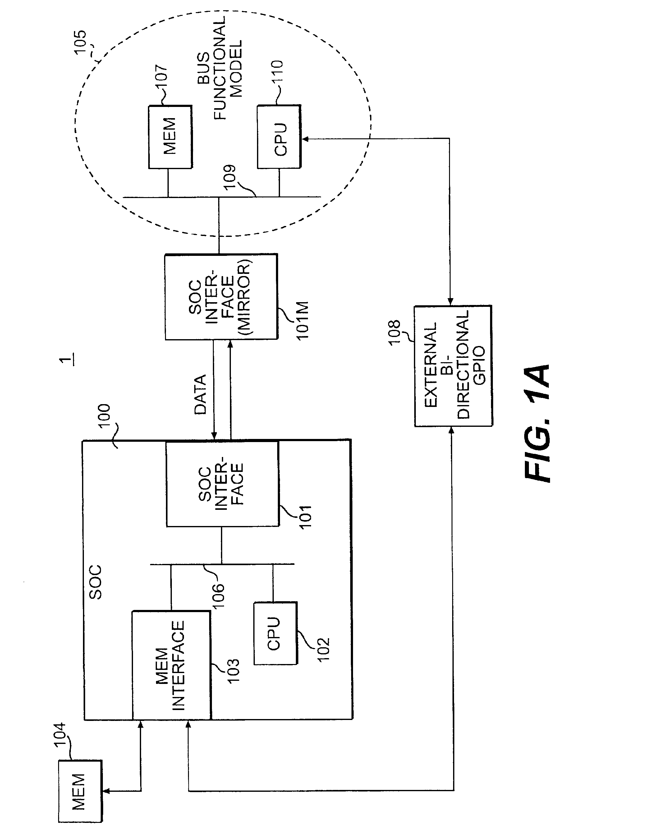
FIG. 1A shows an embodiment of the present invention in the form of a verification test bench 1. The term “test bench” is well known in the simulation / verification field, and refers to a compiled and simulation-ready computer program including a model or models to be simulated. A verification test bench provides all of the external stimulus needed to test a SOC or part of an SOC, and receives stimulus from the SOC. The test bench is provided with the stimulus for a particular test case, and then compiled by a simulator. The simulator loads the compiled test bench into the simulator to conduct the test case.

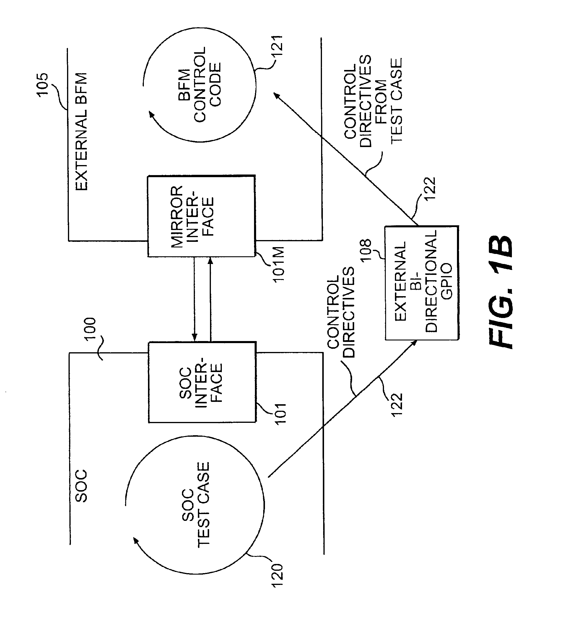
Thus, FIG. 1A (and FIGS. 1B and 2, discussed in greater detail below) are to be understood, in general terms, as representing a software simulation of a physical system. Accordingly, when terms such as “connected,”“attached” or “coupled,” as represented by lines connecting block elements in the Figures, are used in the following, reference is being made to a software counterpart o...


PUM


Abstract

Verification of external interfaces of cores on system-on-chip (SOC) designs frequently entails the purchase of costly standardized software models to test the external interfaces. Typically, the standardized models provide more functionality than is needed. Instead of standardized models, test models may be developed and utilized, but this also incurs cost and delay. The present invention provides an efficient and economical alternative. A mirror interface, or copy of the external interface undergoing verification, is used with a standardized control mechanism to verify the external interface. Because all interface I / O connections can thereby be utilized, a cost-effective and highly reusable way of verifying such interfaces is provided.

Description

BACKGROUND OF THE INVENTIONThe present invention relates generally to the verification of integrated circuit (IC) logic, and more particularly to a method and system for increasing the efficiency and re-usability of verification software.Before ICs are released to market, the logic designs incorporated therein are typically subject to a testing and de-bugging process known as “verification.” Verification of logic designs using simulation software allows a significant number of design flaws to be detected and corrected before incurring the time and expense needed to physically fabricate designs.Software verification typically entails the use of software “models” of design logic. Such models may be implemented as a set of instructions in a hardware description language (HDL) such as Verilog® or VHDL®. The models execute in a simulation environment and can be programmed to simulate a corresponding hardware implementation. The simulation environment comprises specialized software for in...

Claims


Application Information

Patent Timeline
08 Mar 2005
Publication
US6865502B2
IPC
G01R31/28; G01R31/319
CPC
G01R31/318357; G06F17/5022; G01R31/319; G06F30/33
Inventors
DEVINS, ROBERT J.; FERRO, PAUL J.