
Method of manufacturing strain-detecting devices

Inactive Publication Date: 2005-03-15
NAGANO KEIKI
View PDF6 Cites 7 Cited by
  • Summary
  • Abstract
  • Description
  • Claims
  • Application Information

AI Technical Summary

Benefits of technology

The present invention has been made in view of the above circumstances, and an object of the present invention is, therefore, to provide a method of manufacturing strain-detecting devices, which is able to precisely position substrates on a jig, thus allowing gage patterns to be formed highly accurately on the diaphragm of each substrate, with a manufacturing cost still suppressed.
It is preferred that the method further comprises the step of disassembling the fixing pate from the jig, including a step of separating each of the substrates from the fixing plate by cutting the elastic members after forming the strain gage portions. Only cutting the elastic members allows the substrates, which function as strain-detecting devices, to be separated from the fixing plate in an easier manner.

Problems solved by technology

However, the foregoing conventional manufacturing methods have faced various problems.
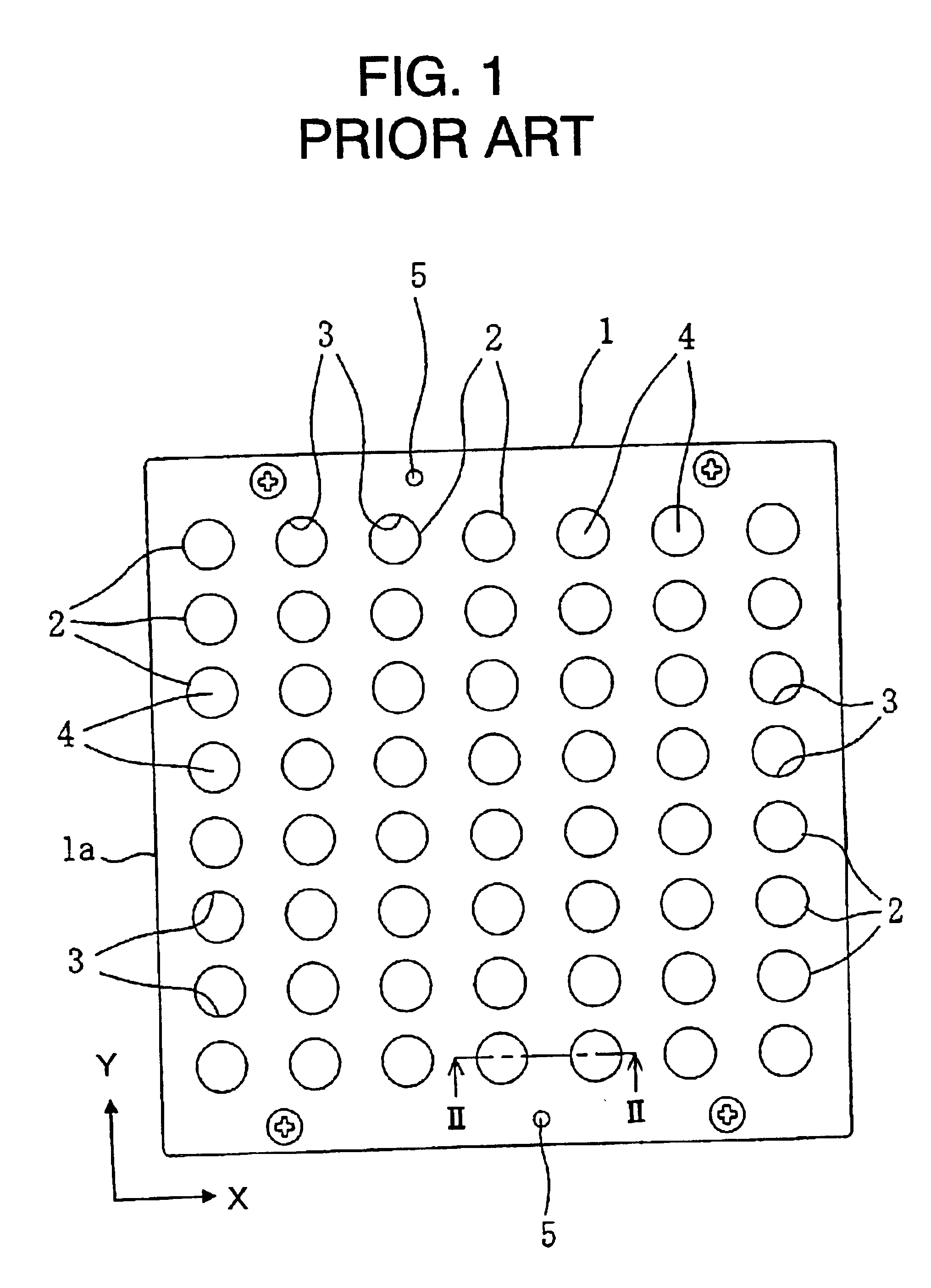
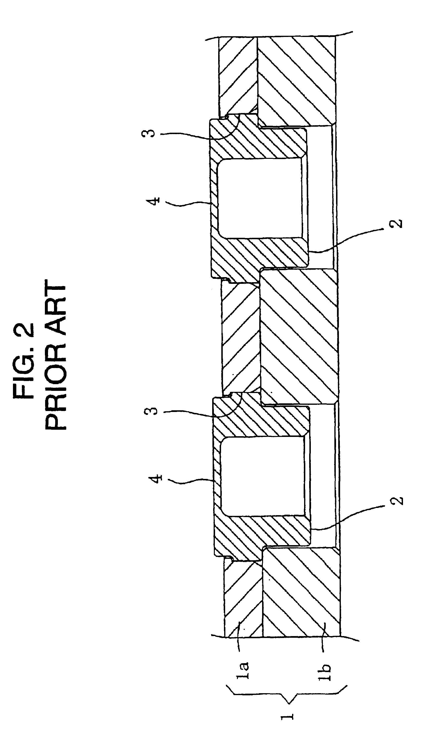
In the former manufacturing method shown in FIGS. 1 and 2, a first problem comes from the shape of each substrate 2.
It is therefore difficult to position each substrate 2 in its rotating direction.
A second problem results from a gap between each substrate 2 and the jig 1.
That is, the strain gages cannot be placed in place on each diaphragm 4, being a defective device.
A third problems is therefore that the cost of manufacturing strain-detecting devices has been high, because of higher degrees of finishing precision of both of the jig 1 and the substrates 2.
On the other hand, the foregoing latter manufacturing method represented by FIGS. 3 and 4 is also accompanied by a number of problems.
A first problem is also concerned with a manufacturing cost.
A second problem results from the fact that each pin 6 is pressed into the bottomed opening (cavity) of each jig 7.
There are some cases where pressing the pin 6 into the opening damages the surface of the opening, thus decreasing the reliability of the devices themselves.
If such damaged strain-detecting devices are applied to, for example, pressure vessels, the reliability of the pressure vessels themselves will be spoiled as well.
These drawbacks will also lead to unstable factors in enhancing the reliability.
Further, a third problem is caused by the configuration in which each pin 6 is pressed into the bottomed opening of each substrate 2.
The residue of such fluids often brings about a pollutant problem in the various post-steps for manufacturing strain-detecting devices.

Method used


Image

  • Method of manufacturing strain-detecting devices
  • Method of manufacturing strain-detecting devices
  • Method of manufacturing strain-detecting devices

Examples


Embodiment Construction

A preferred embodiment according to the present invention will now be described with reference to FIGS. 5 to 15.

First, strain-detecting devices manufactured by a manufacturing method of the present invention will be exemplified.

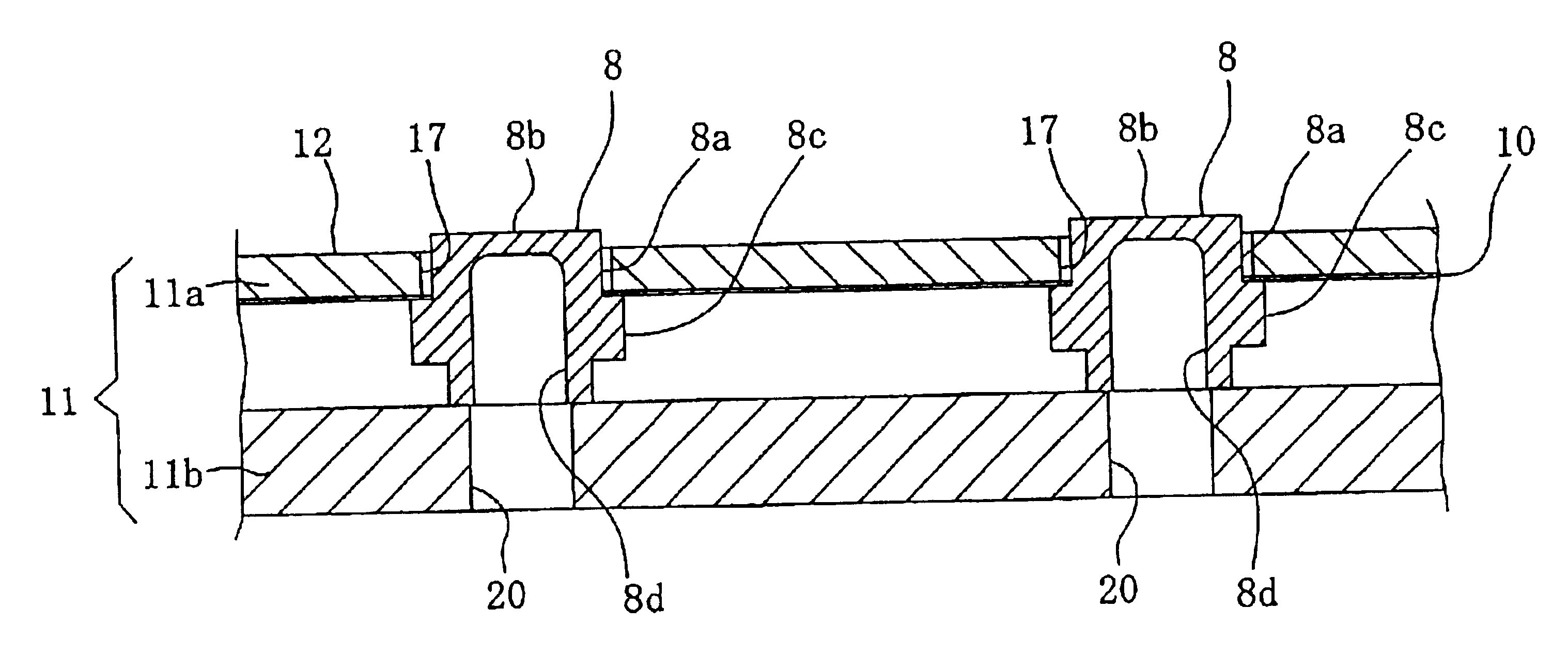
FIG. 5 exemplifies a strain-detecting device SG, which is equipped with a substrate 8 and a strain gage portion 9 formed on the substrate 8.

The substrate 8, which is formed into a single rigid body made of a given metal material, has a cylindrical pillar 8a having both ends in its axial direction. As shown in FIGS. 5 and 6, one end is integrally closed with a thin plate, while the other end is opened. The part of the thin plate functions as a diaphragm 8b.

Further, a cavity (bottomed opening) 8d with an aperture at one end is formed in the cylindrical pillar 8a. When fluid is administered into the cavity 8d as illustrated by an arrow A in FIG. 5, the pressure of the fluid acts on the back of the diaphragm 8b, thereby causing the diaphragm 8b to be deformed. A...


PUM

PropertyMeasurementUnit
Timeaaaaaaaaaa
Thicknessaaaaaaaaaa
Levelaaaaaaaaaa

Abstract

A method of manufacturing strain-detecting devices is provided. First, plural cylindrical substrates, each of which has one end closed by a diaphragm, are fixedly placed at predetermined positions of a fixing plate. A positioning marker is previously given to the fixing plate. The fixing plate having the substrates is then assembled into a jig. The jig sustains the substrates so that an outer surface of the diaphragm of each substrate is held at the same level. Through positioning the substrates, all the diaphragms are then positioned in place in a plane direction of the fixing plate with reference to the positioning marker. A strain gage portion is simultaneously formed on each of all the diaphragms. The fixing plate is then disassembled from the jig. In this step, the substrates with the strain gage portions, i.e., strain-detecting devices, are separated from the fixing plate.

Description

CROSS REFERENCE TO RELATED DOCUMENTThis application claims the benefit of Japanese application 2001-332863 filed Oct. 30, 2001.BACKGROUND OF THE INVENTIONThe present invention relates to a method of manufacturing strain-detecting devices.Elements for detecting strain are categorized into a variety of types of elements. One type of strain-detecting device uses a diaphragm on which a strain gage is arranged. The diaphragm responds to stimulation that has been given, and the strain gage senses the stimulation based on physical changes in the diaphragm. Such strain-detecting devices have been manufactured by using various types of methods.Referring to FIGS. 1 and 2, one type of manufacturing method will now be described. As shown therein, a jig 1 made up of upper and lower plates 1a and 1b are used. This jig 1 is made to have lot of holes 3 formed at given positions thereof. The holes 3 are responsible for sustaining substrates 2 of the strain-detecting devices with precision concerning...

Claims


Application Information

Patent Timeline
IPC IPC(8): G01L1/22G01L9/00G01L1/20G01L9/04
CPCG01L1/2287G01L9/0051Y10T29/49007Y10T29/49998Y10T29/43Y10T29/49877Y10T29/49103
Inventor HATA, YUKIHIKOYAMAURA, KUNIHIRONAGASAKA, HIROSHI
Owner NAGANO KEIKI
Learn More