Door cylinder lock

a technology of door cylinders and locks, applied in the direction of keyhole guards, mechanical control devices, instruments, etc., can solve the problems of increased installation and maintenance costs, more susceptible to accidental or ill-intended damage, etc., and achieve the effect of great flexibility

Inactive Publication Date: 2005-03-15
GOLDMAN & CO INC
View PDF34 Cites 78 Cited by
  • Summary
  • Abstract
  • Description
  • Claims
  • Application Information

AI Technical Summary

Benefits of technology

The cylinder lock of the present invention is designed as a modular structure. All electronic control circuits, sensors, drives, batteries, etc. are concentrated in one detachable module which is the inner handle. A second module is a housing accommodating the inner and outer plugs, the rotary cam and the clutch. Due to the nature of the unblocking signal that is transmitted as a vibration through the body of the door lock, or through a light-guide, or as radio waves, the second module has no electric or electronic parts requiring connections to the first module. After mounting the second module in the door, the first module can be assembled to the second by simple screws, bolts or other means without disassembling the door lock and without disconnecting and connecting signal or power lines in the door lock.
The modularity of the cylinder lock constitutes considerable convenience in the assembly of new door locks or in retrofitting existing door locks. The modularity also provides for great flexibility in changing the access level of individual rooms by replacing the inner handles.

Problems solved by technology

They are more expensive for installation and maintenance and more susceptible to accidental or ill-intended damage.

Method used


Image

  • Door cylinder lock
  • Door cylinder lock
  • Door cylinder lock

Examples


Embodiment Construction

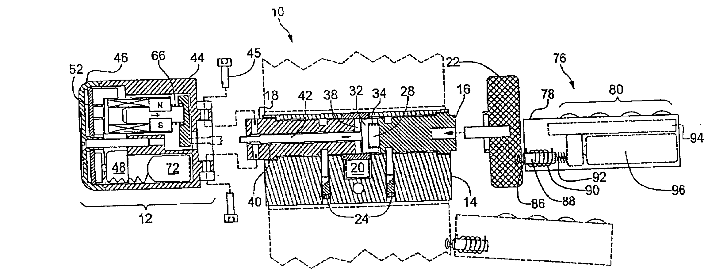
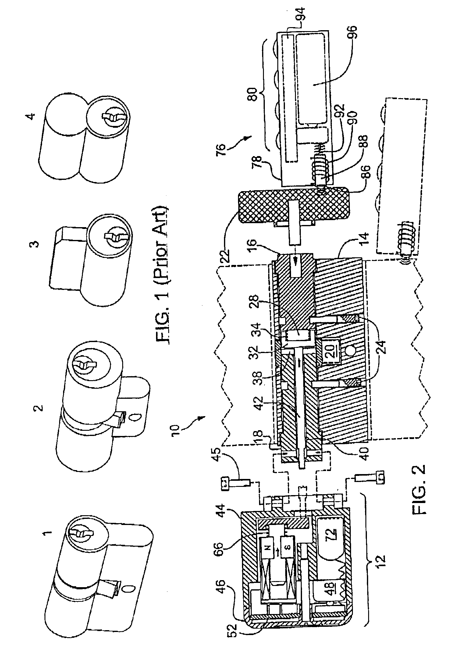
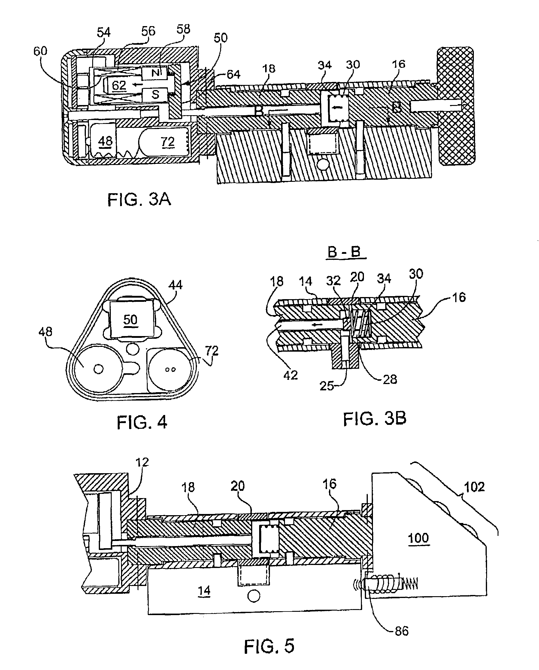
With reference to FIGS. 2, 3A, 3B and 4, a cylinder door lock 10 of the present invention comprises a handle assembly 12, a housing 14 with an outer plug 16, an inner plug 18 and a rotary cam 20, and an outer knob 22. The handle assembly 12 is attached to the inner plug 18. The housing 14 and the rotary cam 20 have the size and the form of a standard cylinder lock and can be retrofitted in any standard door lock. A standard door lock is locked by a deadbolt which, under the action of the rotary cam 20, can slide into a notch in the doorframe (the door lock, the deadbolt and the doorframe are not shown). In the following, it is assumed that the handle assembly 12 is at the inner side of the door (room side), while the outer plug 16 and the outer knob 22 face the outer side (corridor or street side).

The two plugs 16 and 18 are rotatably accommodated in the housing 14 together with the rotary cam 20 and are held in place by two retaining bolts 24 that allow only rotation of the plugs. ...


PUM


Abstract

A cylinder lock for use in a door lock, comprising an outer plug, an inner plug, a rotary cam adapted to move a deadbolt of the door lock, and a clutch adapted to engage for rotation the outer plug to the rotary cam. The cylinder lock further comprises an electronic blocking device (EBD) and a drive adapted to actuate the clutch upon an unblocking command from the EBD generated upon receiving therein an unblocking signal emitted from the outer side of the door, thereby enabling moving the deadbolt by rotation of the outer plug. The cylinder lock comprises an inner handle attached thereto at the inner side of the door, the EBD and the drive being entirely accommodated within the inner handle. The signal is emitted by an electronic key or panel and may be a mechanical vibration signal, a light signal, or a radio signal.

Description

FIELD OF THE INVENTIONThis invention relates to door cylinder locks, and specifically to electronic door locks that are opened by coded input signal.BACKGROUND OF THE INVENTIONCylinder locks are widely known and used as locking mechanisms in doors, windows, boxes, cases, drawers, safes, padlocks, bicycle locks, etc. The mechanical cylinder lock has one or two cylinder-shaped plugs rotatable by an inserted key to move a locking bolt from the door into the door frame or backwards, thereby locking or unlocking the door. The mechanical varieties of cylinder locks are standardized to allow mass production and convenient replacement and retrofitting of existing doors. Examples of conventional mechanical cylinder locks such as Euro Profile cylinder lock 1, Swiss cylinder 2, and Schlage® cylinders 3 and 4 are shown in FIG. 1.Electronic locks are also known. Some electronic locks have a keypad control panel near the door or on the door itself, which is used to input an entry code. Other type...

Claims


Application Information

Patent Timeline
Patent Type & Authority Patents(United States)
IPC IPC(8): E05B47/06E05B13/00E05B17/00E05B63/00E05B47/00G07C9/00
CPCE05B47/0615E05B47/0642E05B47/068G07F17/145E05B13/005E05B17/0087E05B47/0004Y10S292/27E05B2047/0079E05B2047/0091E05B2047/0094G07C2009/00769E05B63/0056Y10T70/7706Y10T70/5496Y10T70/5416Y10T70/7073Y10T70/7062Y10T70/5805Y10T70/7079Y10T70/5827Y10T70/7107E05B47/06
Inventor GOLDMAN, ILAN
Owner GOLDMAN & CO INC
Why Eureka
Try Eureka