Automated docking of space vehicles

Inactive Publication Date: 2005-03-15
LOCKHEED MARTIN CORP
View PDF22 Cites 60 Cited by
  • Summary
  • Abstract
  • Description
  • Claims
  • Application Information

AI Technical Summary

Benefits of technology

In view of the foregoing, a broad objective of the present invention is to facilitate automated docking of space vehicles. Another objective of the present invent

Problems solved by technology

Unfortunately, there are many factors that cause this procedure to be done in less than ideal conditions.
First of all, the pilot is typically not able to directly view the portions of the vehicles that are being docked together, such as through a window.
Further, the image quality may suffer due to lighting constraints.
Also, it is possible for the optics to become fogged due to moisture or contaminated due to chemical deposition, thus washing out the image.
First of all, the pilot may not be as comfortable maneuvering the space vehicle while viewing only radar imaging as opposed to video imaging or direct viewing.
Further, the measurement by the radar of range to the other vehicle, range rate, and direction may not be sufficiently precise.
Also, there is typically not much in the way of attitude or angular orientation information available from radar imaging systems.
Unfortunately, the transmission delays inherent in transmitting video, range, range rate, and direction information to the ground and then transmitting command and control information from the ground operator back to one of the space vehicles make such a procedure difficult.
Any type of control loop would be negatively affected by such delays.
Further, there are few opportunities for direct communication between the space vehicles and the ground operators.
When direct communication from the space vehicle to the ground operators is not possible, then additional transmission delays are incurred d

Method used


Image

  • Automated docking of space vehicles
  • Automated docking of space vehicles
  • Automated docking of space vehicles

Examples


Embodiment Construction

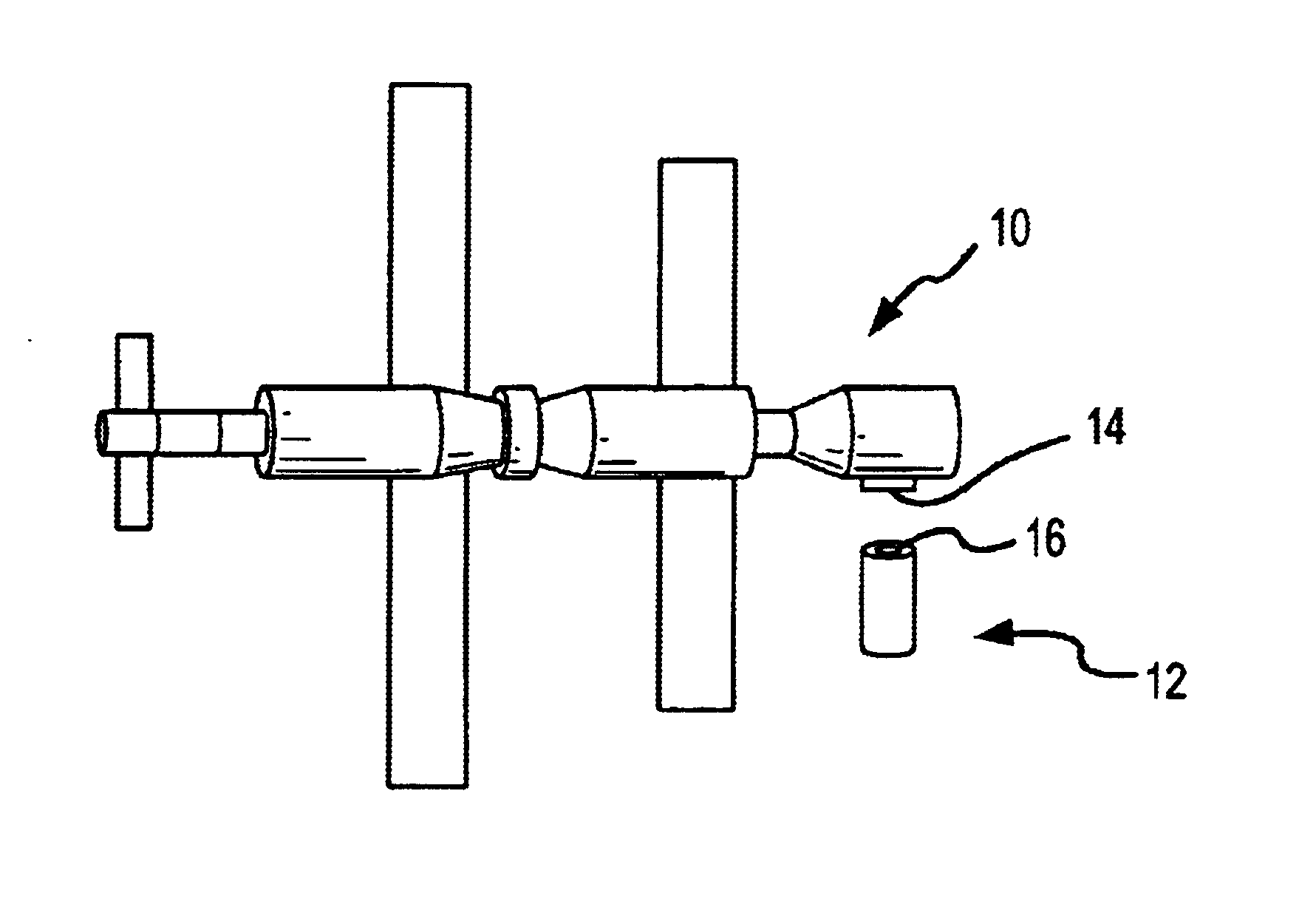
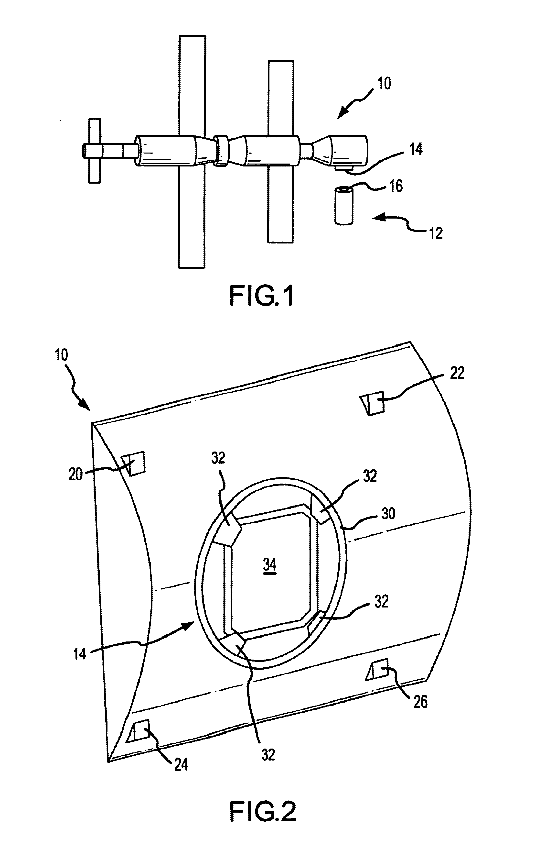
Reference will now be made to the accompanying drawings, which assist in illustrating the various pertinent features of the present invention. Although the present invention will now be described primarily in conjunction with space vehicles, it should be expressly understood that the present invention may be applicable to other applications where positioning two or more objects in an automated fashion is required / desired. In this regard, the following description of an automated docking system for space vehicles is presented for purposes of illustration and description. Furthermore, the description is not intended to limit the invention to the form disclosed herein. Consequently, variations and modifications commensurate with the following teachings, and skill and knowledge of the relevant art, are within the scope of the present invention. The embodiments described herein are further intended to explain modes known of practicing the invention and to enable others skilled in the art...


PUM


Abstract

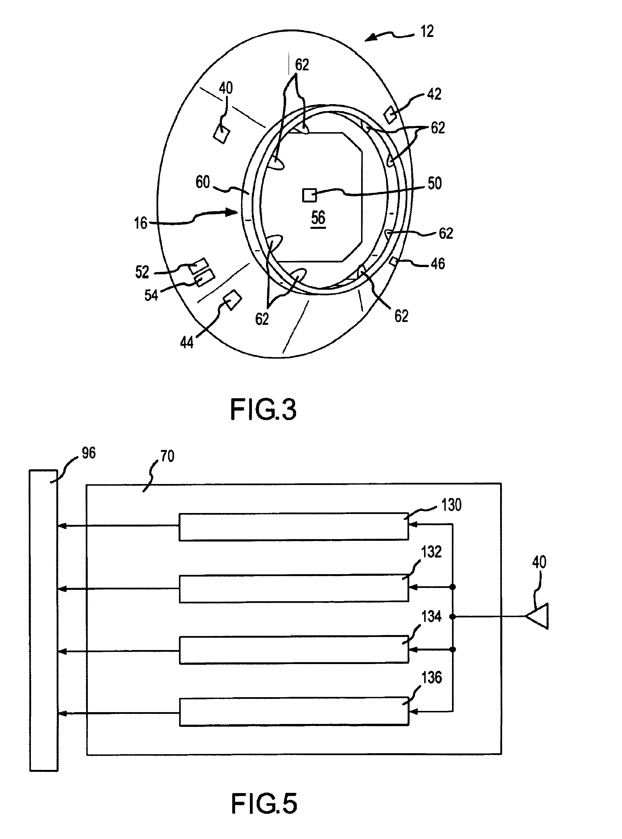
An automated docking system for space vehicles that includes a plurality of antennas on each of a target vehicle and a chase vehicle. A pseudo random code is transmitted via one of the antennas located on one of the vehicles and received by one of the antennas located on the other vehicle. The pseudo random code is then sent back to the original vehicle via transmissions from the plurality of antennas on the second vehicle and received by the plurality of antennas on the original vehicle. The distance from each of the antennas on the other vehicle to each of the antennas on the originating vehicle can be measured in this fashion. The antennas on each of the vehicles are located in a spaced-apart arrangement so that the angular orientation or attitude of each of the vehicles to each other can also be determined. A plurality of video cameras is provided on the exterior of one of the vehicles and video information from these cameras is transmitted to the other vehicle for display to operators in that vehicle. Commands between the vehicles can also be communicated.

Description

FIELD OF THE INVENTIONThis present invention relates generally to techniques for use in docking space vehicles, and more particularly to techniques for use in an automated process of docking vehicles based on an exchange of RF signals between multiple antennas on each of the space vehicles.BACKGROUND OF THE INVENTIONThere is a continuing need to improve procedures for docking one space vehicle to another space vehicle. Once these space vehicles are in close proximity to each other, some current systems rely on a pilot in one of the vehicles who makes use of radar and / or vision systems while steering one of the vehicles relative to the other vehicle. Unfortunately, there are many factors that cause this procedure to be done in less than ideal conditions. First of all, the pilot is typically not able to directly view the portions of the vehicles that are being docked together, such as through a window. Instead, the pilot is typically viewing a radar or video display. In the case of a ...

Claims


Application Information

Patent Timeline
IPC IPC(8): B64G1/24B64G1/64
CPCB64G1/242G05D1/12B64G1/646
Inventor FINNEY, RICHARD
Owner LOCKHEED MARTIN CORP
Why Eureka
Try Eureka