Electrical cable and connection structure between electrical cable and terminal

Inactive Publication Date: 2005-03-15
SUMITOMO WIRING SYST LTD
View PDF3 Cites 5 Cited by
  • Summary
  • Abstract
  • Description
  • Claims
  • Application Information

AI Technical Summary

Benefits of technology

Thus, the electrical connection portion welded by the iron based welding material forms the conductor and insulation displacement terminal by substituting the aluminum-based metal for the conventional copper

Problems solved by technology

This requires extensive manpower and is not practical.
Th

Method used


Image

  • Electrical cable and connection structure between electrical cable and terminal
  • Electrical cable and connection structure between electrical cable and terminal
  • Electrical cable and connection structure between electrical cable and terminal

Examples


Embodiment Construction

In describing the preferred embodiment of the present invention, reference will be made herein to FIGS. 1 to 5 of the drawings in which like numerals refer to like features of the invention. Features of the invention are not necessarily shown to scale in the drawings.

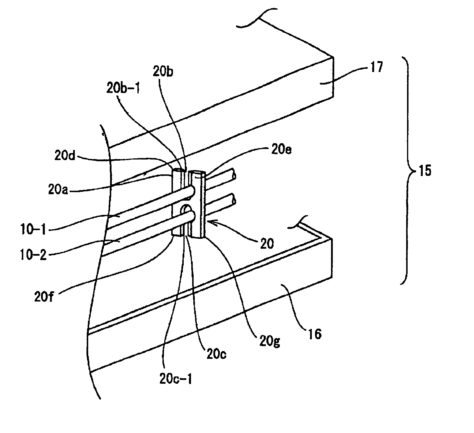
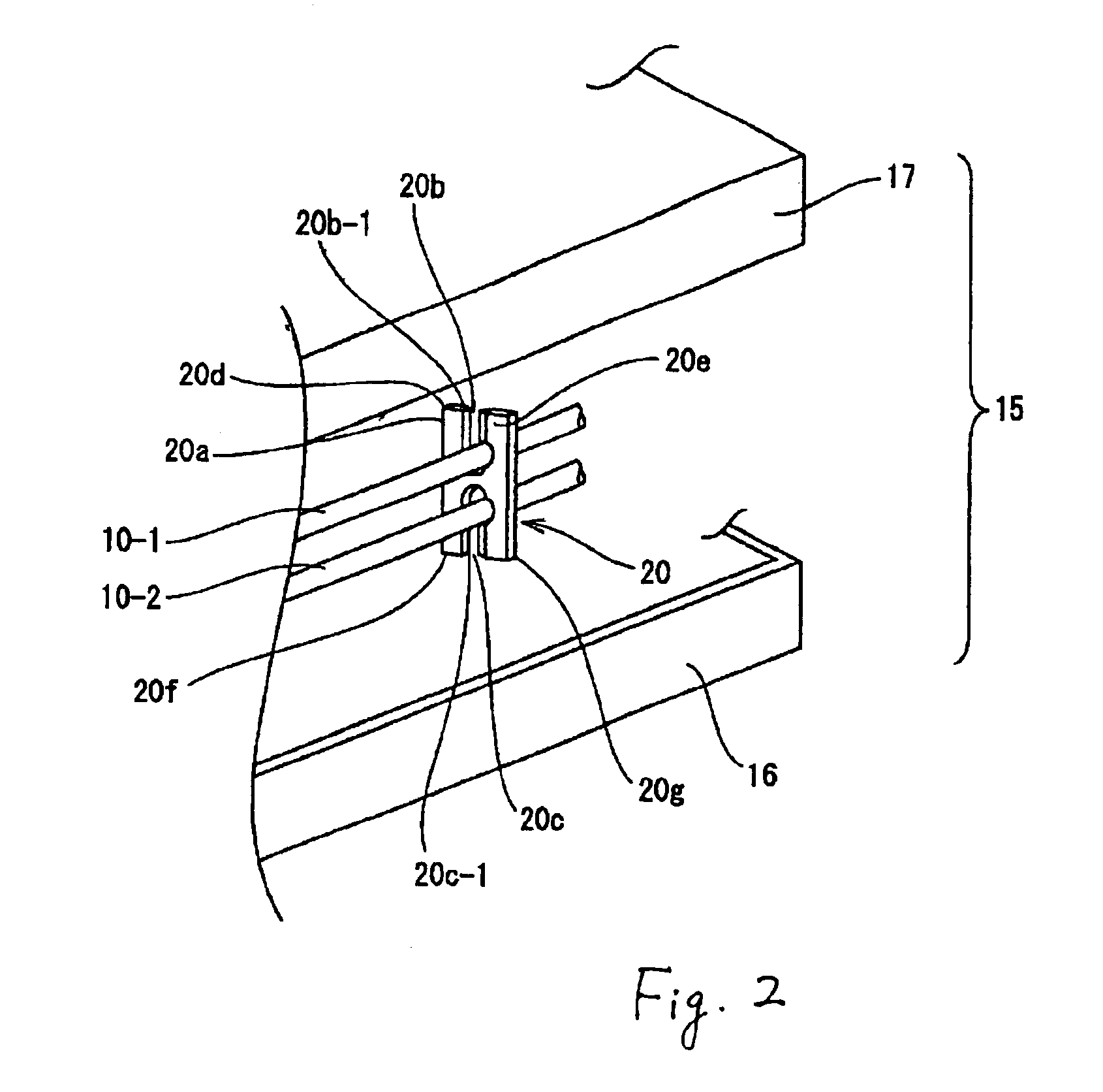
Embodiments of an electrical cable and a connection structure between the electrical cable and a terminal in accordance with the present invention will be described below by referring to the drawings.

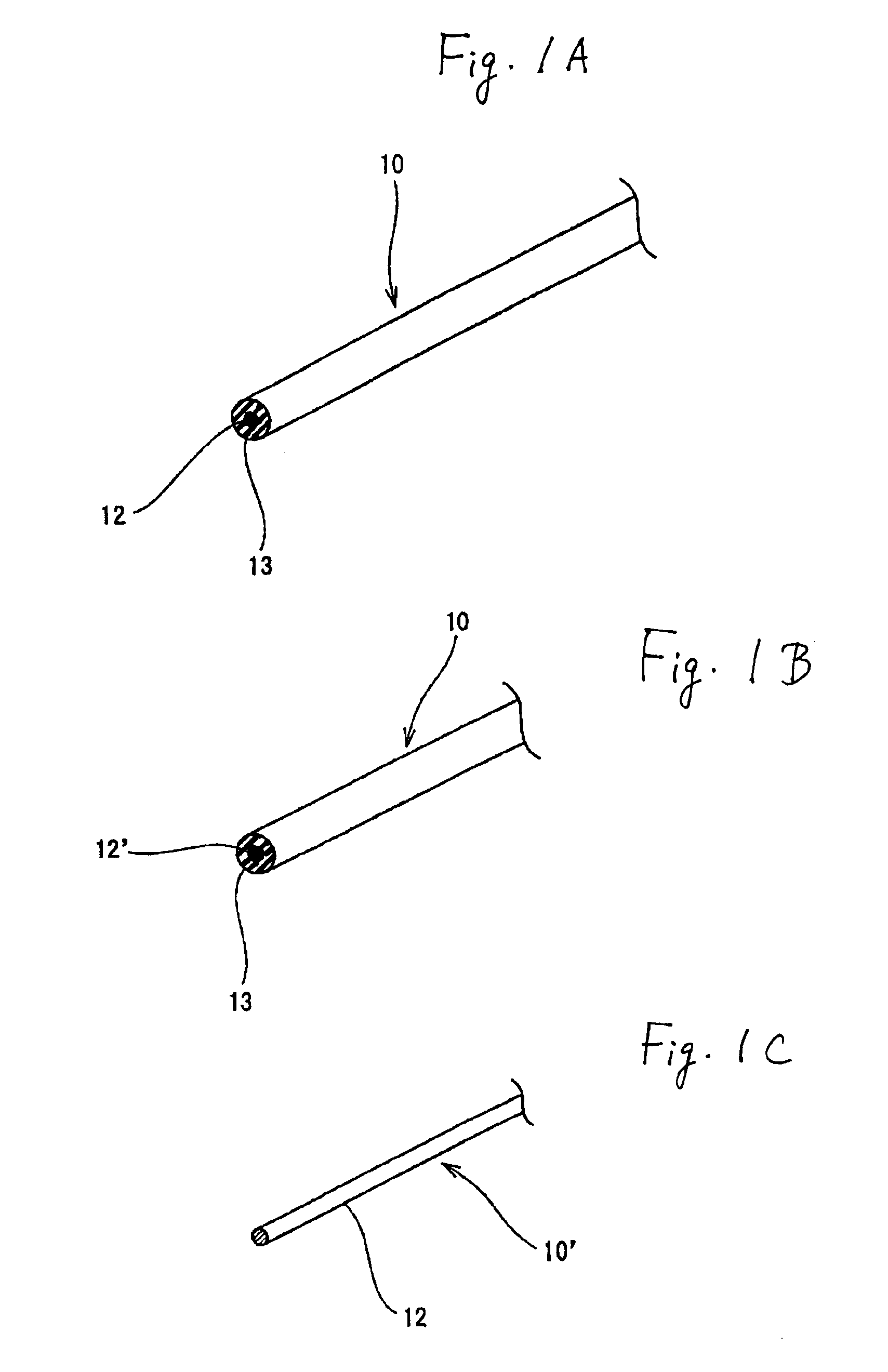
FIG. 1A shows an electrical cable 10 in accordance with the present invention.

The electrical cable 10 includes a single core wire or a conductor 12 made of an aluminum-based metal and an insulation sheath layer 13 made of a PE (or PBT) having a heat resistant nature covering the conductor 12. As shown in FIG. 1B, a conductor 12′ may be a twisted core wire formed by twisting a number of fine element wires. Furthermore, the electrical cable may be a so-called naked cable 10′ in which the conductor 12 is not covered by the ins...


PUM


Abstract

An electrical cable is used to form an internal circuit in an electrical connection box to be mounted on an automobile. An aluminum-based metal conductor is covered with a heat-resistant resin, such as PE (polyethylene) or PBT (polybutylene terephthalate). The conductor is a single core wire or a twisted core wire, which has a plurality of element wires. The conductor is pushed into an insulation displacement slot in an insulation displacement terminal. The insulation displacement terminal is made from an aluminum-based metal or a copper-based metal. A welding material, made of an iron-based metal, welds a contact portion between the conductor and a blade section on an inner peripheral edge of the insulation displacement slot.

Description

CROSS-REFERENCE TO RELATED APPLICATIONSThis application claims priority to Japanese Patent Application No. 2002-259189, filed Sep. 4, 2002, which application is herein expressly incorporated by reference.FIELD OF THE INVENTIONThis invention relates to an electrical cable and a connection structure between the electrical cable and a terminal. More particularly, the invention improves electrical cable used to form an internal circuit in an electrical connection box, such as a junction box, mounted on an automobile, in view of its recyclability upon junking an automobile.BACKGROUND OF THE INVENTIONA number of electrical cables are arranged in an automobile. The electrical cables are also arranged in the electrical connection box, such as a junction box, to form an internal circuit.For convenience of explanation, a conventional electrical cable and a connection structure between the conventional electrical cable and a terminal will be described by referring to FIG. 6. FIG. 6 is a perspe...

Claims


Application Information

Patent Timeline
IPC IPC(8): H01R4/00H01R4/04H01R4/24H01B7/02B60R16/02H01B7/29H02G3/16
CPCH01R4/04H01R4/245H01R4/242
Inventor YUASA, ERIKOYAMAKAWA, SHUJI
Owner SUMITOMO WIRING SYST LTD
Why Eureka
Try Eureka