Self-dividing oscillators

Active Publication Date: 2005-03-15
CALIFORNIA INST OF TECH
View PDF1 Cites 39 Cited by
  • Summary
  • Abstract
  • Description
  • Claims
  • Application Information

AI Technical Summary

Benefits of technology

The present invention provides many important technical advantages. One important technical advantage of the present invention is a self dividing oscillator that uses injection

Problems solved by technology

The phase noise performance of oscillators is a factor in the overall system performance of many communication systems, such as in its effect

Method used


Image

  • Self-dividing oscillators
  • Self-dividing oscillators
  • Self-dividing oscillators

Examples


Embodiment Construction

In the description that follows like parts are marked throughout the specification and drawings with the same reference numerals, respectively. The drawing figures are not necessarily to scale and certain features may be shown in somewhat generalized or schematic form in the interest of clarity and conciseness.

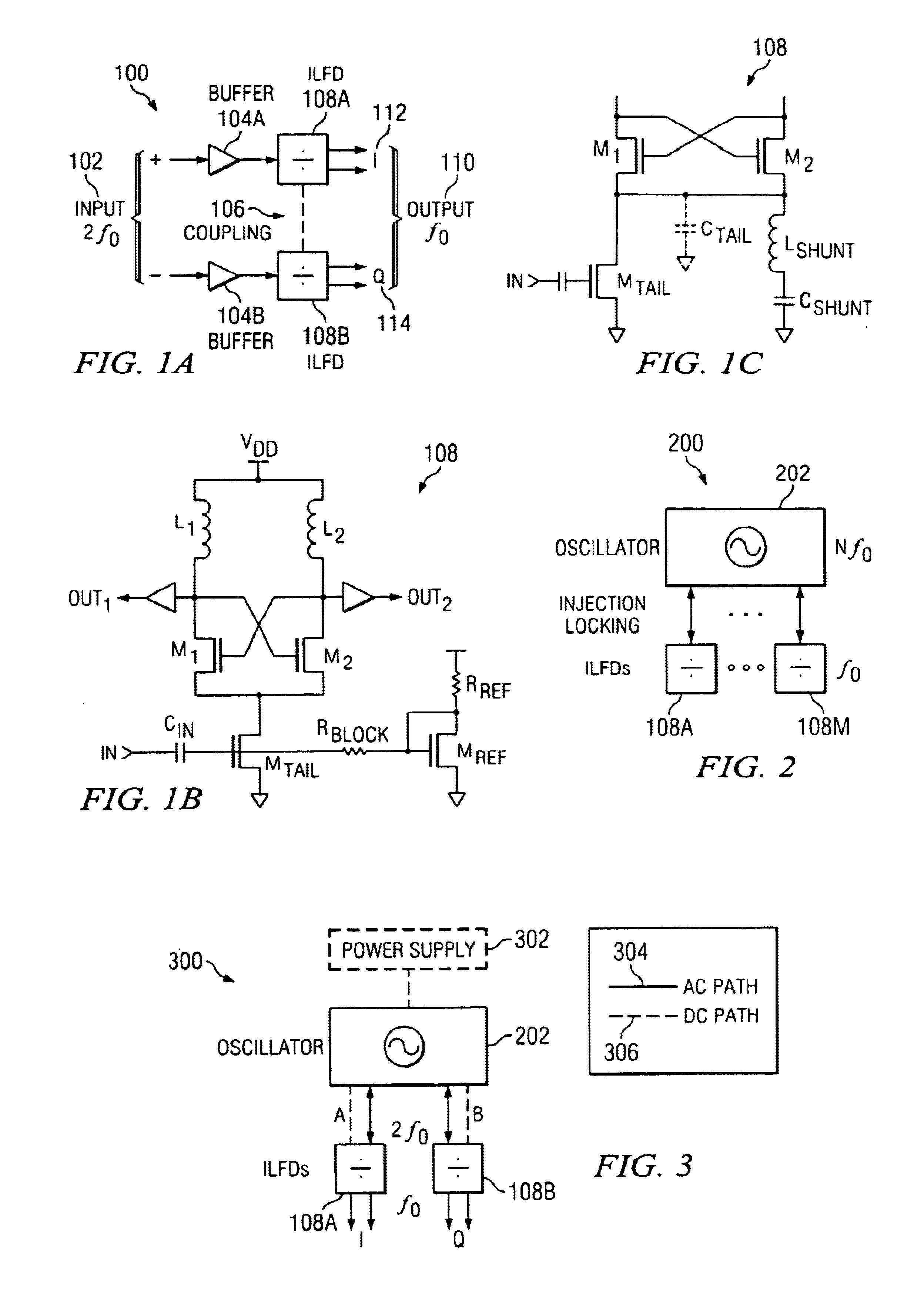
FIG. 1A is a diagram of a system 100 for providing in-phase and quadrature phase signals using injection-locked frequency dividers in accordance with an exemplary embodiment of the present invention. A differential input 102 receives a signal having a frequency of 2×f0, such as from an oscillator. Buffers 104A and 104B can be used to buffer the input signal. Injection-locked frequency dividers 108a and 108b are then driven by differential input 102 to generate outputs 110 having a free running frequency centered at f0. Injection-locked frequency dividers 108A and 108B can be injection-locked by the input signals. The outputs of injection-locked frequency dividers 108A and 108B...


PUM


Abstract

A system for generating in-phase and quadrature phase signals is provided. The system includes a first and a second differential output, such as from a sinusoidal oscillator. A first injection-locked frequency divider, such as one that uses an LC oscillator in conjunction with cross-coupled transistors, receives the first differential output and generates a in-phase or in-phase output. A second injection-locked frequency divider receives the second differential output and generates a quadrature phase output.

Description

FIELD OF THE INVENTIONThe present invention pertains to oscillators, and more specifically to a self-dividing oscillator with improved efficiency and phase noise performance.BACKGROUND OF THE INVENTIONOscillators are building blocks in modern wireless and wireline communications systems. One important factor in designing oscillators is frequency stability, which is usually quantified as phase noise. Phase noise performance is particularly important in oscillators. The phase noise performance of oscillators is a factor in the overall system performance of many communication systems, such as in its effect on interference in adjacent wireless communications channels. Control of phase noise is also of importance in oscillators that are implemented as integrated circuits, such as part of integrated transceivers. The efforts to improve phase noise performance for integrated oscillators have focused on increasing the quality factor, “Q,” of the resonator, among other things.Oscillators are...

Claims


Application Information

Patent Timeline
IPC IPC(8): H03L7/24H03B5/08H03B5/12H03B27/00
CPCH03B27/00H03L7/24H03B5/1243H03B5/1215H03B5/1228
Inventor HAJIMIRI, SEYED-ALIWU, HUI
Owner CALIFORNIA INST OF TECH
Why Eureka
Try Eureka