
System for guiding the visually handicapped

a technology for visually impaired people and systems, applied in repeater circuits, instruments, line-transmission details, etc., can solve problems such as unsatisfactory systems of this type, and achieve the effects of improving navigation efficiency, facilitating use, and alleviating the uneasiness of visually impaired persons

Inactive Publication Date: 2005-03-15
NANAYAKKARA PRAVIN L +2
View PDF12 Cites 25 Cited by
  • Summary
  • Abstract
  • Description
  • Claims
  • Application Information

AI Technical Summary

Benefits of technology

It is accordingly an object of the present invention to provide a guiding device for the visually handicapped, due to blindness or an environmental conditions such as lack of illumination, fog, smoke or the like to obviate the need for a walking cane or, alternatively, if a walking cane is employed, enhance the ease of use thereof to effect efficient navigation between points within areas and structures both public and private.
It is another object to provide a system of the above type to render blind persons less obvious when they are in public places.
It is a further object of the invention to provide a system and method for alleviating the uneasiness of visually impaired persons when they are seeking to reach destinations within areas that they are otherwise unfamiliar with.
It is another object to provide a system for guiding of the blind that may be incorporated fully within an article of clothing, such as a shoe, of the user, thereby eliminating entirely the need for use of a walking cane.

Problems solved by technology

Systems of this type have, however, proven unsatisfactory due to difficulty in the interpretation of the types of signals returned in which a user can often confuse background objects with objects that are in the foreground.

Method used


Image

  • System for guiding the visually handicapped
  • System for guiding the visually handicapped
  • System for guiding the visually handicapped

Examples


Embodiment Construction

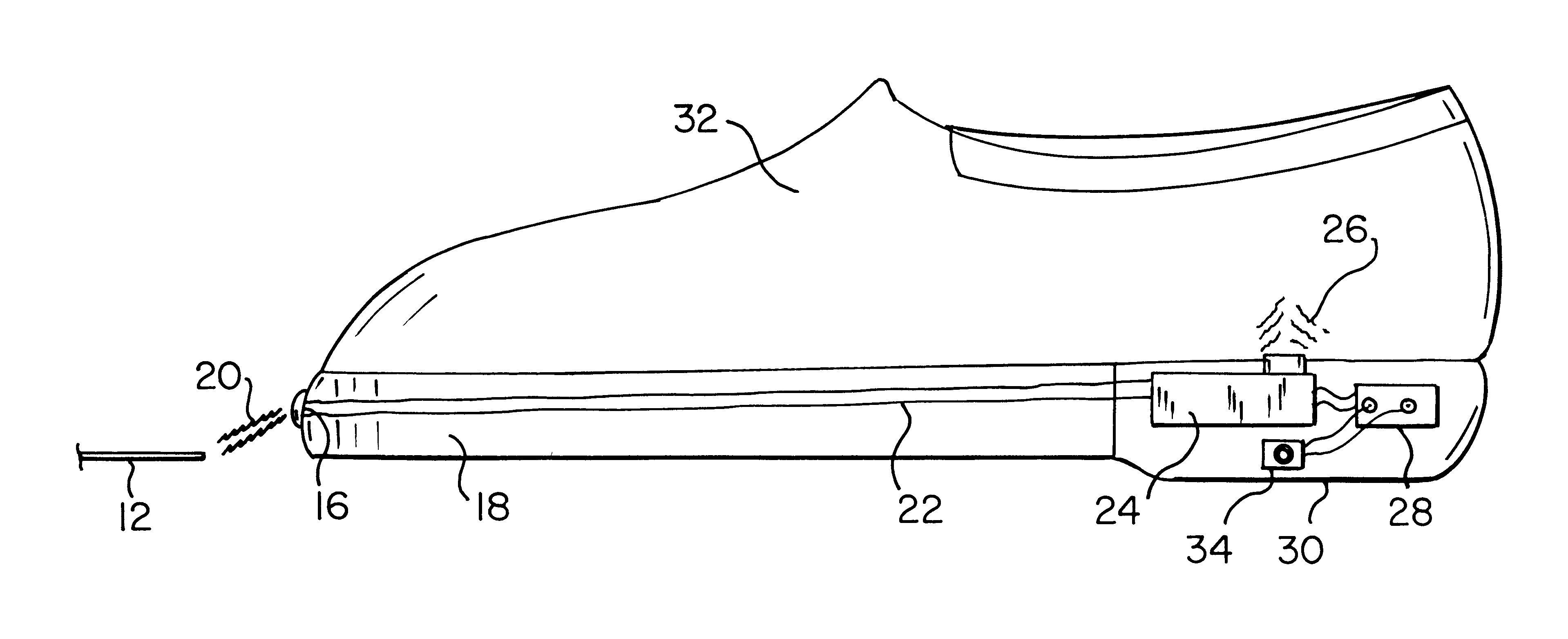
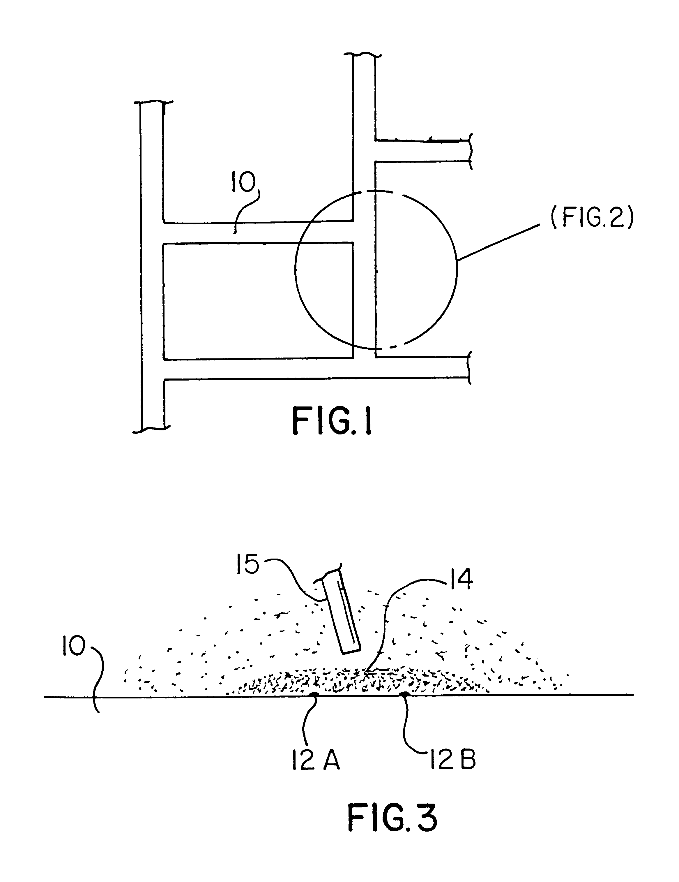
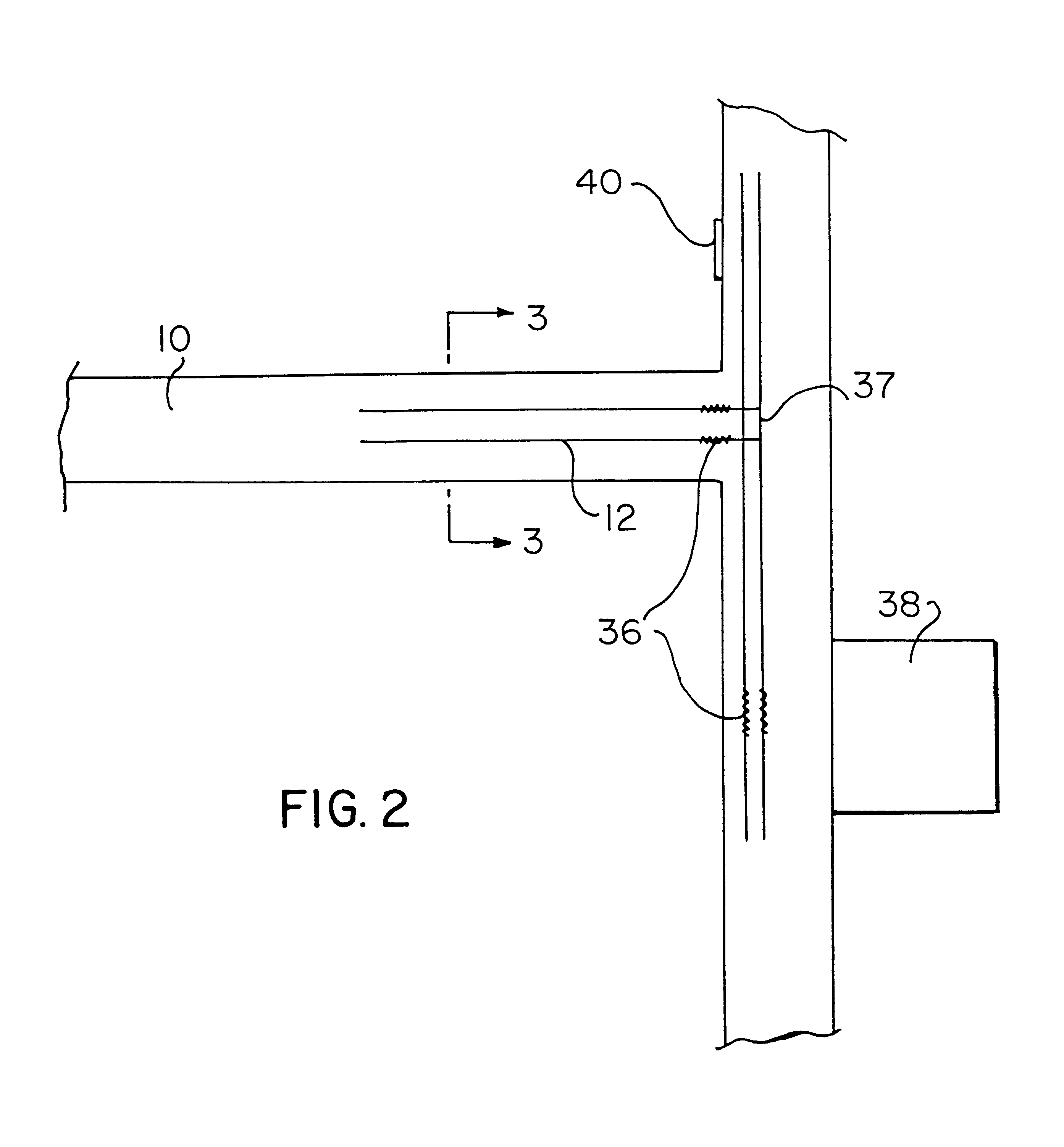
With reference to the overhead schematic view of FIG. 1, there may be seen a plurality of walkways 10 which may comprise walkways within public or private structures, residences, or walkways within an outdoor area, e.g., a downtown section of a city street. Embedded within each walkway or applied at substantially the surface thereof is a continuous electrical conductor 12 of substantially uniform electrical conductivity. See enlarged schematic view of FIG. 2. It has, in a preferred embodiment, been found that parallel pairs of metal conductors 12 will afford redundancy for purposes of the invention and will also enlarge the range of conductive material detecting means, as is set forth below.

Such sensors, and proximity sensors in general, operate upon a principle of response to changes in capacitance or inductance when introduced into a field 14 of a probe 15. See FIG. 3. When the necessary range setting of the probe is met, an alarm will trigger within a particular distance from the...


PUM


Abstract

A system for guiding of the visually handicapped includes a continuous electrical conductor, in the nature of a wire or strip, having a substantially uniform conductivity embedded within a walkway to be traversed by the handicapped person. The system also including a proximity for detecting the conductor in which the detector may be in a shoe of the user or a tip of a walking cane. The system further includes a signalling element, in the nature of a vibrator, in electrical communication with the detector such that, through the presence of such vibration, the visually handicapped person is able to determine his proximity to the electrical conductor to determine that he is proceeding in a proper direction within or along the walkway. The signalling element is preferably provided with a switch, for example, a mercury switch, so that the shoe or cane circuit will become energized only upon the occurrence of movement or motion of the shoe or cane within which the proximity detector is located. The approach by a user to a location of interest along the walkway, such as an intersection, bathroom, or Braille telephone, may be indicated through the provision of a pattern of irregularity of the conductivity within the continuous electrical conductor. Different patterns of irregularity may indicate different advisories to the user.

Description

BACKGROUND OF THE INVENTION1. Area of InventionThe invention relates to guiding devices for use by persons including, but not limited to, the blind, visually impaired, security personnel, emergency personnel and fire fighters.2. Prior ArtGuiding devices have been designed in which a signal is sent out from the device and is reflected from an object positioned above the walking level and returned to the device, this in the manner of a simplified type of radar or sonar to thereby operate a signalling means to indicate to the user that an object is in front of him. Systems of this type have, however, proven unsatisfactory due to difficulty in the interpretation of the types of signals returned in which a user can often confuse background objects with objects that are in the foreground. Such prior art is reflected in U.S. Pat. No. 3,360,775 (1967) to Schroeder.A later device of this type is reflected in U.S. Pat. No. 3,718,896 (1973) to Moat in which, provided within a blindman's cane i...

Claims


Application Information

Patent Timeline
IPC IPC(8): A61H3/06A61H3/00G09B21/00G08G1/005
CPCA61H3/061A61H3/066A61H3/068G09B21/007G08G1/005A61H2003/065A61H2003/063
Inventor NANAYAKKARA, PRAVIN L.NANAYAKKARA, ANYA R.NANAYAKKARA, LAKDAS
Owner NANAYAKKARA PRAVIN L
Learn More