
Frequency regulation of an oscillator for use in MWD transmission

a technology of frequency regulation and oscillator, which is applied in the field of measuring while drilling (mwd) systems, can solve problems such as bleeding pressur

Inactive Publication Date: 2005-03-15
COLLETTE HERMAN D
View PDF3 Cites 24 Cited by
  • Summary
  • Abstract
  • Description
  • Claims
  • Application Information

AI Technical Summary

Benefits of technology

The present invention reduces the poppet force and stroke required of the poppet, thereby reducing the size, cost, and weight or the MWD tool. Reducing the force and stroke demanded of the poppet also substantially increases its useful life by reducing wear.

Problems solved by technology

When the bistable valve becomes upset it changes state, in the case of unseating the valve, pressure is bled from within the drive cylinder, this also bleeds the pressure that upset the bistable valve in the first place.

Method used


Image

  • Frequency regulation of an oscillator for use in MWD transmission
  • Frequency regulation of an oscillator for use in MWD transmission
  • Frequency regulation of an oscillator for use in MWD transmission

Examples


Embodiment Construction

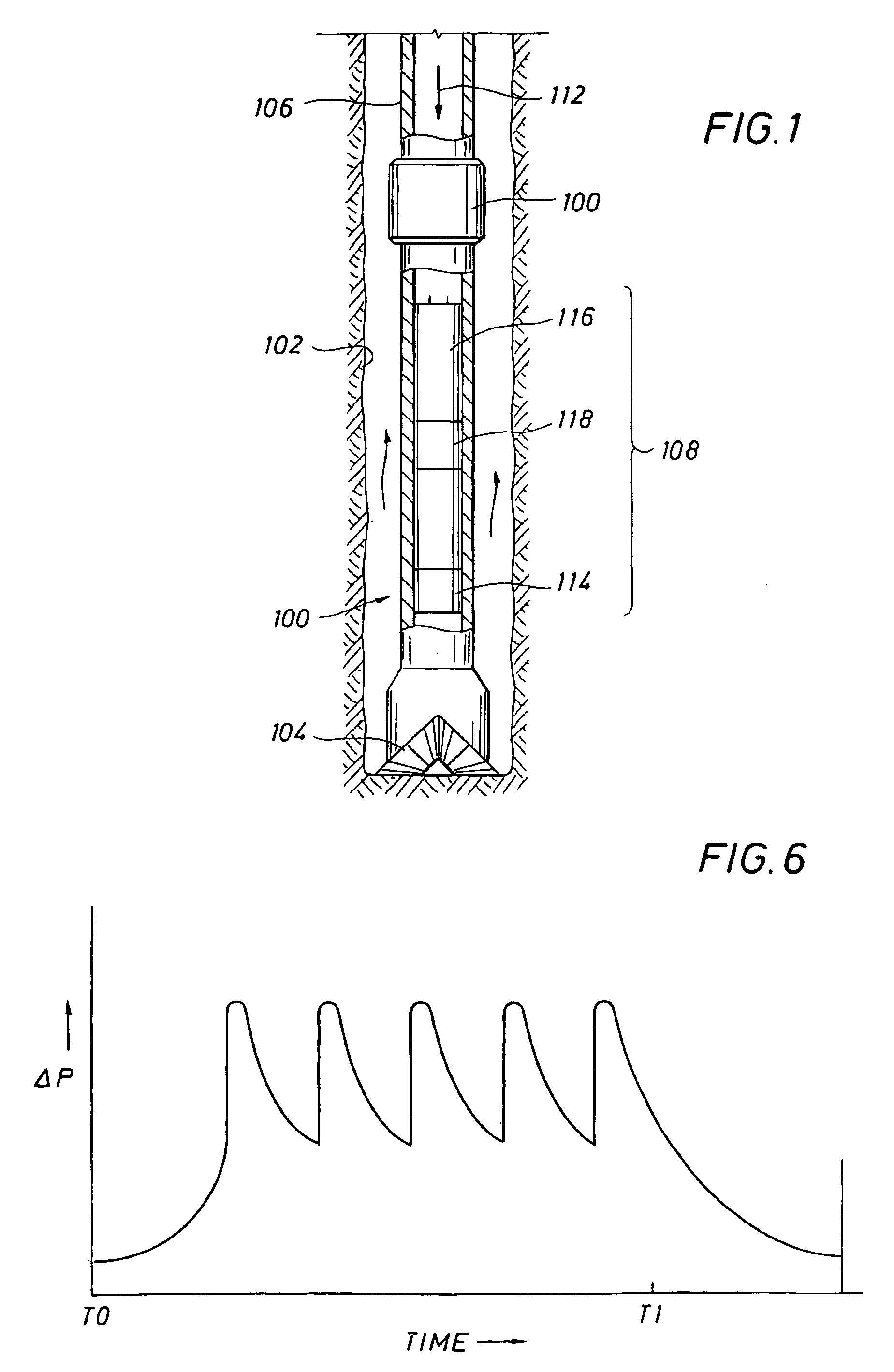
FIG. 1 illustrates a basic drilling system 100 in a bore hole 102 formed by a typical drill bit 104. The drill bit 104 is driven by a drill pipe 106 which joins to a bottom hole assembly 108 with a coupling 110. Drilling mud flows down through the drill pipe 106, as shown by an arrow 112, through the bottom hole assembly 108, through the drill bit 104 and back to the surface by way of the annulus between the drill pipe and the bore hole.

The bottom hole assembly 108, between the coupling 110 and the drill bit 104, is where the present invention finds application. The bottom hole assembly 108 includes one or more sensors 114 adapted to measure parameters of interest. The sensor(s) 114 provide a sensor signal to a transmitter 116 which includes a pulser 118. The transmitter 116 and pulser 118 vary the pressure in the drilling fluid, which variation is detected at the surface and interpreted to provide the measured data at the surface. These sensors provide an output to a control unit (...


PUM


Abstract

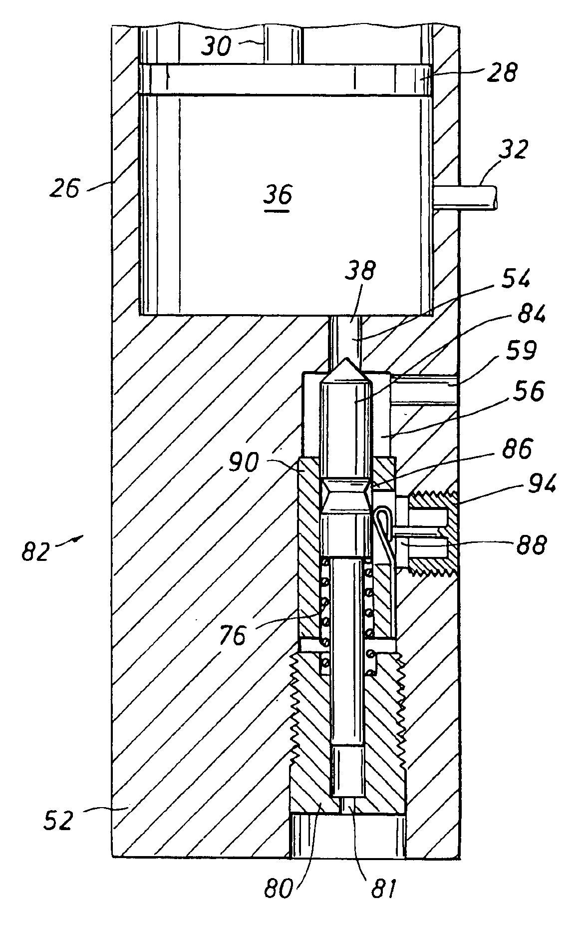
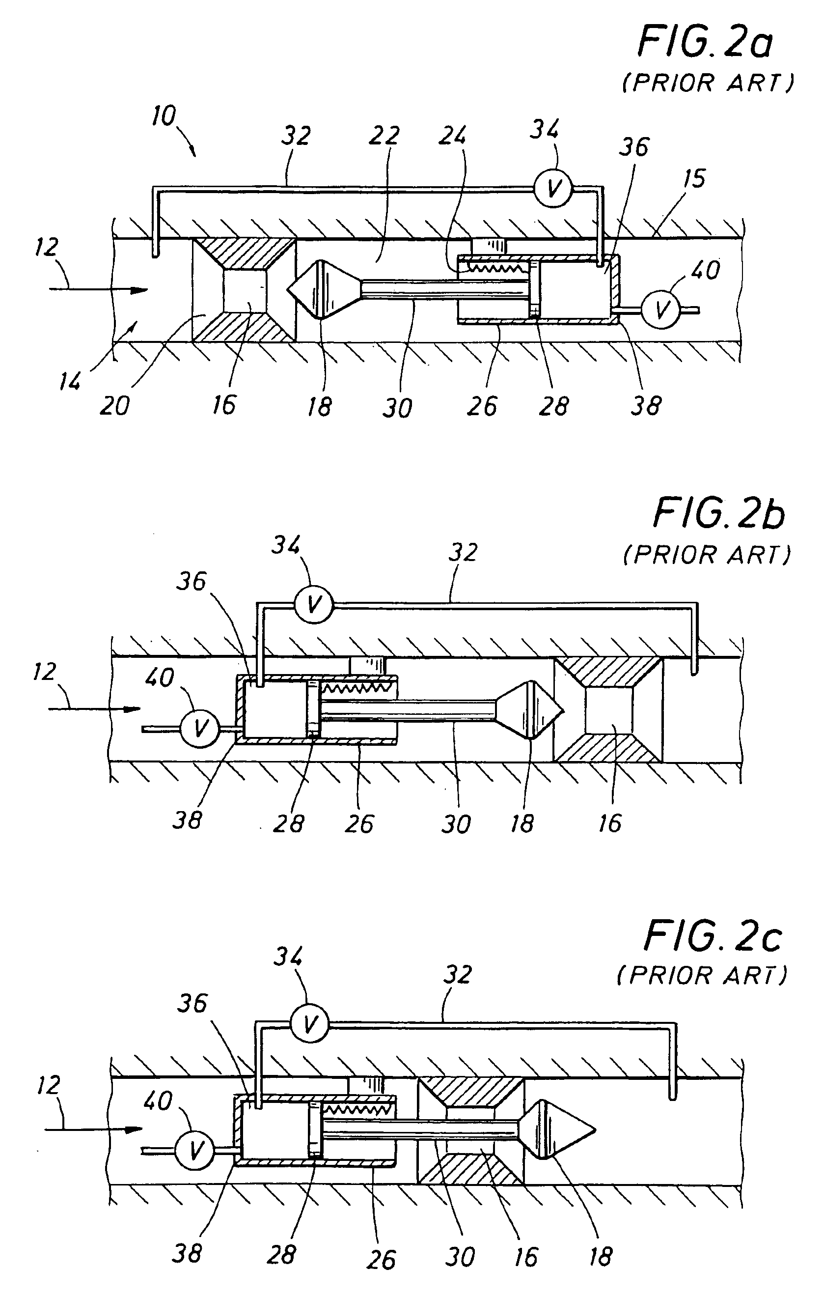
An oscillating valve driven by the pressure in a mud pulser develops a pressure variation in the mud pulse signal that is at a frequency that is different than the frequencies of the mud system. The oscillating valve is coupled to or integral with the pulse drive cylinder, whether the drive means for operation of the pulser is upstream or downstream from the orifice, or whether or not the drive means and the poppet are on the same side or opposite sides of the orifice. The oscillating valve is a bistable valve which preferably forms one wall of the drive piston of the pulser. Pressure from the drive cylinder behind the drive piston is directed in such a way as to unseat the bistable valve. When the bistable valve unseats, pressure is bled from within the drive cylinder, which also bleeds the pressure that unseated the bistable valve in the first place. When pressure drops, the bistable valve reseats, and the cycle repeats as long as pressure is being ported to the cylinder, thereby creating a tone in the drilling mud.

Description

FIELD OF THE INVENTIONThe present invention relates generally to the field of measuring while drilling (MWD) systems, and, more particularly, to a system which provides repeated, cyclic pressure oscillations in the transmission of data from borehole sensors to receivers at the surface.BACKGROUND OF THE INVENTIONRemotely operated sensor packages have been used during the drilling of wells for a number of years. These packages are commonly found in drilling applications where information such as the inclination, azimuth, and various logging sensor measurements of the well are of interest.During well drilling operations, drilling fluid, known in the art as drilling mud, is typically pumped down through the drill pipe and then through the drill bit to clean, lubricate, and cool the bit. The drilling fluid then returns to the surface by way of the annulus between the drill pipe and the bore hole or casing, where the drilling mud is cleaned of cuttings so that the drilling fluid can be re...

Claims


Application Information

Patent Timeline
IPC IPC(8): E21B47/18E21B47/12G01V11/00
CPCG01V11/002E21B47/187E21B47/24
Inventor COLLETTE, HERMAN D.
Owner COLLETTE HERMAN D
Learn More