
Image-taking apparatus, and camera and camera system incorporating it

a technology which is applied in the field of image-taking apparatus and camera system incorporating it, can solve the problems of high cost, large amount of information, and high cost of high-resolution image sensor, and achieve the effect of large apertur

Active Publication Date: 2005-03-15
MINOLTA CO LTD
View PDF4 Cites 42 Cited by
  • Summary
  • Abstract
  • Description
  • Claims
  • Application Information

AI Technical Summary

Benefits of technology

An object of the present invention is, by exploiting the advantages of a fovea lens, to provide an image-taking apparatus provided with a high-performance taking lens system that has a large aperture but that nevertheless is compact.

Problems solved by technology

Attempting to obtain an image without distortion even in a peripheral portion thereof with a wide-angel lens having a total angle of view over 60° results, due to an increased number of lens elements and other factors, in complicating the construction of the optical system, leading to higher costs.
Attempting to record a super-wide-angle image with uniformly high definition results in handling a huge amount of information, necessitating an expensive high-resolution image sensor.
Such an increase in the amount of information to be handled is undesirable from the viewpoint of quick transfer of data when image information is exchanged in cellular phones, personal information assistants, and the like, which are becoming increasingly popular these days,
The former method complicates the construction of both the optical system and the drive mechanism, leading to higher costs, and the latter method degrades image quality.
Moreover, all those lens elements are glass lens elements, resulting in high costs.
Moreover, they suffer from large residual aberrations and thus unsatisfactory imaging characteristics.
For these reasons, conventional fovea lenses are unsuitable for achieving high image quality, compactness, and low costs.
Moreover, they all have an f-number as low as f4, and it is difficult to give them large apertures.

Method used


Image

  • Image-taking apparatus, and camera and camera system incorporating it
  • Image-taking apparatus, and camera and camera system incorporating it
  • Image-taking apparatus, and camera and camera system incorporating it

Examples


examples

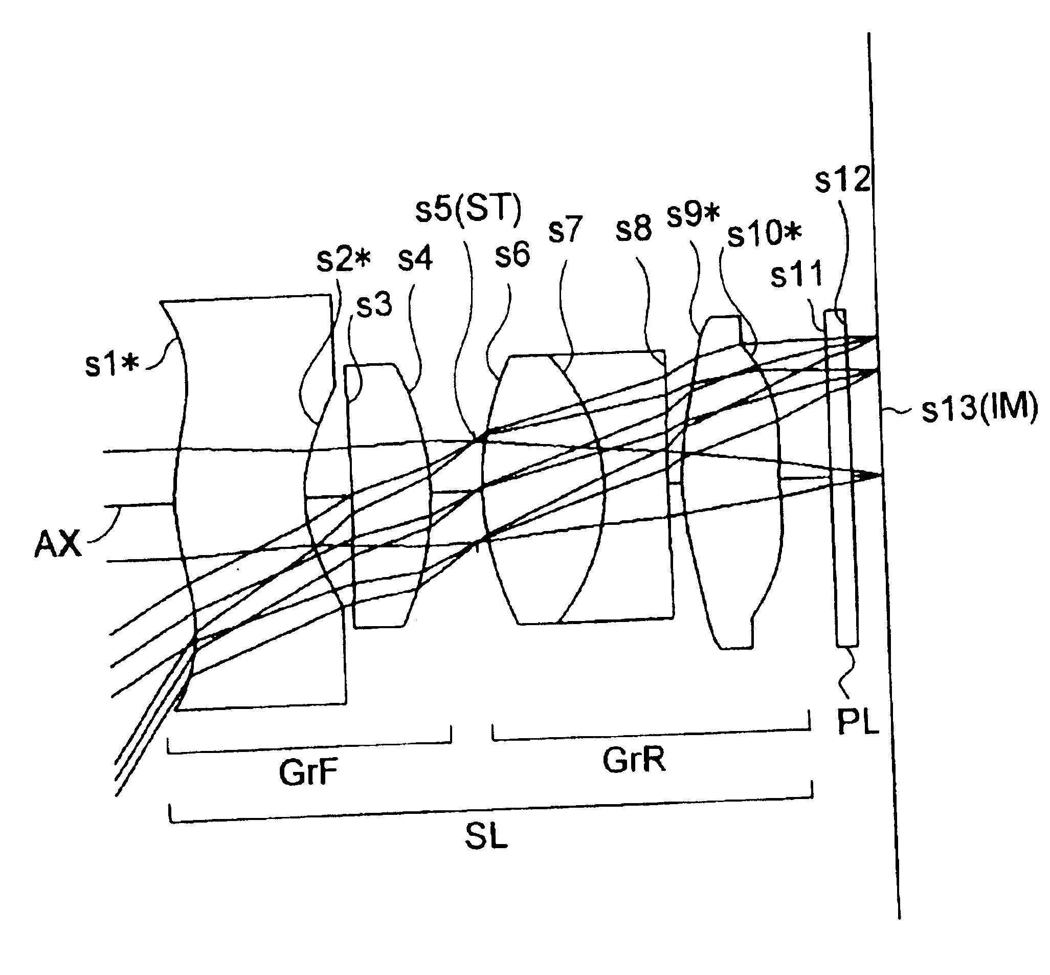
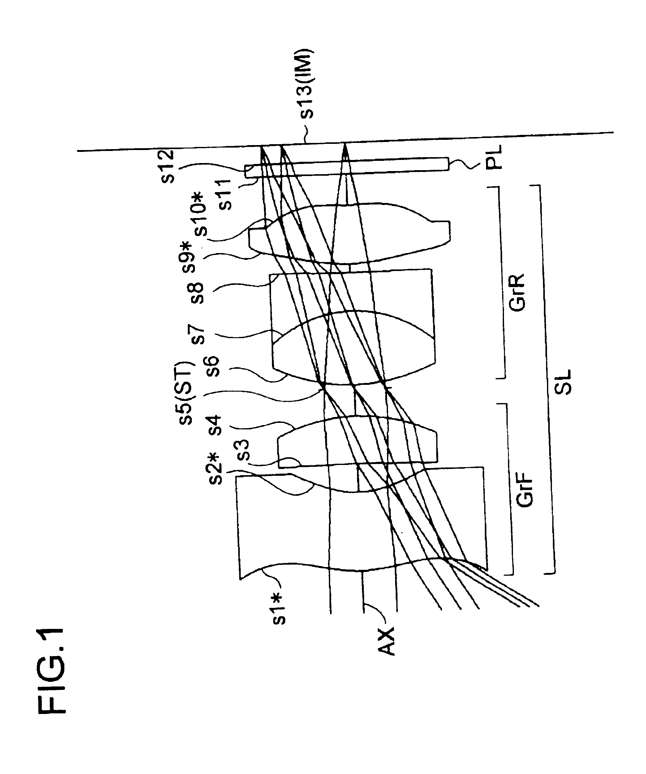
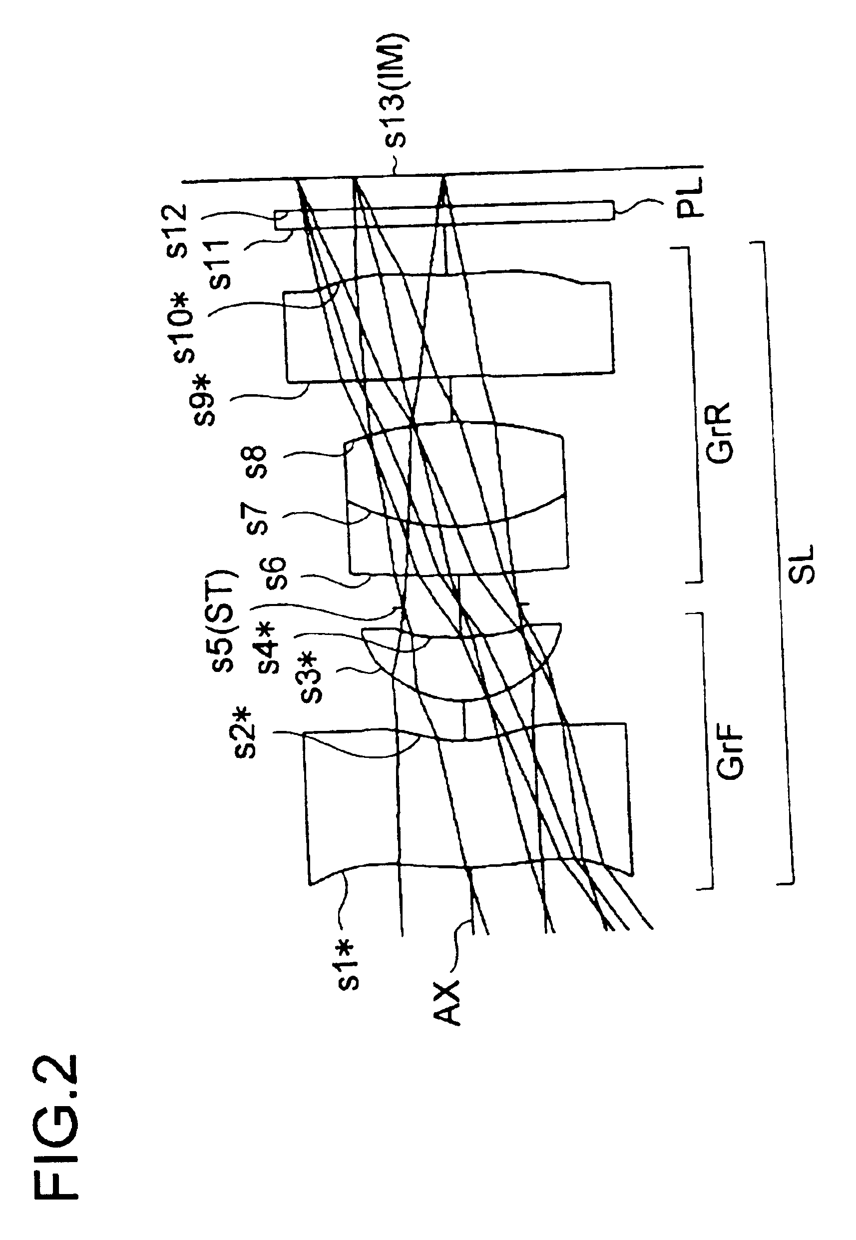
Hereinafter, practical examples of the optical construction and other features of image-taking apparatuses embodying the present invention will be presented with reference to their construction data and other data. Examples 1 to 7 presented below are numerical examples corresponding to the first to seventh embodiments, respectively, described hereinbefore, and therefore the optical construction diagrams (FIGS. 1 to 7) of the first to seventh embodiments also show the lens construction, optical path, and other features of Examples 1 to 7, respectively.

Tables 1 to 7 show the construction data of Examples 1 to 7, respectively. In the construction data of each example, si (i=1, 2, 3, . . . ) represents the i-th surface as counted from the object side (the last surface is the image surface IM), ri (i=1, 2, 3, . . . ) represents the radius of curvature (mm) of the surface si, di (i=1, 2, 3, . . . ) represents the axial distance (mm) between the i-th surface si and the (i+1)th surface si+1...


PUM


Abstract

An image-taking apparatus has an image sensor for converting an optical image into an electrical signal, and a taking lens system for forming the optical image on the light-receiving surface of the image sensor. The most object-side surface of the taking lens system is an aspherical surface that has a positive optical power in a central portion thereof and a negative optical power in a peripheral portion thereof, and the following condition is fulfilled: −90<Da<−20, where Da represents the distortion (%) observed at the maximum half view angle in the diagonal direction of the image sensor.

Description

This application is based on Japanese Patent Application No. 2003-175264 filed on Jun. 19, 2003, the contents of which are hereby incorporated by reference.BACKGROUND OF THE INVENTION1. Field of the InventionThe present invention relates to an image-taking apparatus, and to a camera and a camera system incorporating it. More specifically, the present invention relates to an image-taking apparatus provided with a taking lens system that offers a wide angle of view and simultaneously offers high definition in a central region of a telephoto image, and to a camera and a camera system incorporating such an image-taking apparatus.2. Description of the Prior ArtCommon image-taking apparatuses adopt taking lens systems that have satisfactorily corrected distortion so that there is only a small variation in image magnification between in a central and a peripheral portion of the light-receiving surface (i.e., the image-sensing surface) of an image sensor. Apart from these, there also exist ...

Claims


Application Information

Patent Timeline
Patent Type & Authority Patents(United States)
IPC IPC(8): G02B13/00G02B9/58G02B13/18H04N5/225G02B13/04
CPCG02B9/58G02B13/004G02B13/0045H04N5/232G02B13/18H04N5/2254G02B13/006H04N23/661H04N23/695
Inventor MATSUSAKA, KEIJI
Owner MINOLTA CO LTD
Features
  • Generate Ideas
  • Intellectual Property
  • Life Sciences
  • Materials
  • Tech Scout
  • Unparalleled Data Quality
  • Higher Quality Content
  • 60% Fewer Hallucinations
Learn More