Morphogenetic modelling of in-flight icing

a morphogenetic modelling and in-flight icing technology, applied in the field of fluid behaviour, can solve the problem that the prediction of glaze icing is still not sufficiently accura

Inactive Publication Date: 2005-03-22
NAT RES COUNCIL OF CANADA
View PDF6 Cites 21 Cited by
  • Summary
  • Abstract
  • Description
  • Claims
  • Application Information

AI Technical Summary

Benefits of technology

The invention also provides a system for predicting icing on a surface in a fluid stream, comprising:sensors for measuring predetermined macroscopic physical variables relevant to ice formation in a particular fluid environment;a processor for calculating the behaviour of individual fluid elements

Problems solved by technology

It is generally accepted that the existing models adequately predict rime ice formation, but that the prediction of gl

Method used


Image

  • Morphogenetic modelling of in-flight icing
  • Morphogenetic modelling of in-flight icing
  • Morphogenetic modelling of in-flight icing

Examples


Embodiment Construction

In the description the following terms are employed:

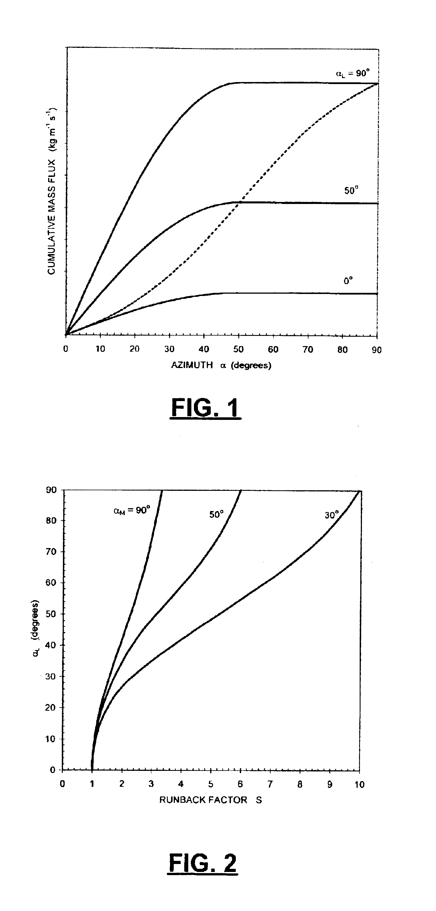
cchord length (m)FrFrössling numberhconvective heat transfer coefficient (Wm−2K−1)kAthermal conductivity of air (W m−1 K−1)LFspecific latent heat of freezing (J kg−1)mwater mass flux along the surface (kg m−1 s−1)mFfreezing mass flux (kg m−2 s−1)mWimpinging water mass flux (kg m−2 s−1)mTtotal incoming water mass (kg m−2)MFjfreezing mass flux per unit length (kg m−1 s−1)MWViimpinging water mass flux on a vertical surface segment per unitlength (kg m−1 s−1)NuNusselt number based on chord lengthPnfreezing probabilityQCconvective heat flux (W m−2)QEevaporative heat flux (W m−2)Qexternal heat flux, Eq. (5) (W m−2)ReReynolds number based on chord lengthsdistance from the stagnation line (m)sRmaximum runback distance (m)Srunback factorttime (s)TAair temperature (K)TSsurface temperature (K)Uuniform airstream velocity (m s−1)Wairstream liquid water content (kg m−3)x, yspatial coordinates (m)αangle between horizontal and normal to airfoil su...


PUM


Abstract

The accretion of ice on an aerodynamic surface is predicted by identifying predetermined atmospheric parameters relevant to ice formation in a particular fluid environment. Then the behaviour of individual fluid elements is simulated based on the identified parameters to create a model of the ice accretion.

Description

BACKGROUND OF THE INVENTION1. Field of the InventionThis invention relates to the field of fluid behaviour, and in particular to a method of predicting in-flight icing of aerodynamic surfaces.2. Description of Related ArtNumerical modelling of the in-flight ice accretion process and its aerodynamic consequences has been performed for several decades to aid in the design of ice protection systems, and in the certification of aircraft for flight in icing conditions. There exists a diversity of advanced two- and three-dimensional icing models that have been developed by various groups in a number of countries (e.g., Bourgault, Y., Beaugendre, H. and Habashi, W. G., 2000. Development of a shallow-water icing model in FENSAP-ICE. AIAA Journal of Aircraft, 37, 4: 640-646; Morency, F., Tezok, F. and Paraschivoiu, I., 1999. Anti-icing system simulation using CANICE. AIAA Journal of Aircraft, 36, 6: 999-1006; Wright, W. B., 1995. Users manual for the improved NASA Lewis ice accretion code LE...

Claims


Application Information

Patent Timeline
IPC IPC(8): B64D15/00B64D15/20
CPCB64D15/20
Inventor SZILDER, KRZYSZTOF
Owner NAT RES COUNCIL OF CANADA
Why Eureka
Try Eureka