Vent damper apparatus

a technology of damper and air intake, which is applied in the direction of fluid heater, light and heating apparatus, furnace-tube steam boiler, etc., can solve the problems of large energy loss through the exhaust flue, loss of approximately 33% of the heat energy generated by the main burner and pilot light operation, and system too costly and cumbersome for widespread domestic us

Inactive Publication Date: 2005-03-22
SCHIMMEYER WERNER
View PDF9 Cites 10 Cited by
  • Summary
  • Abstract
  • Description
  • Claims
  • Application Information

AI Technical Summary

Benefits of technology

In a particularly advantageous embodiment of the invention, the vent damper assembly is structured to limit a range of movement of the plurality of independently mova...

Problems solved by technology

Energy losses through an exhaust flue can be significant; it is estimated that approximately 33% of the heat energy generated from the main burner and pilot light operation is lost directly up the flue.
While effective for that purpose, such devices often require significant exhaust flow in order to open, and thus are useable only with relatively large units, or those equipped with a fan or blower.
Unfortunately, such systems are too costly and cumbersome for widespread domestic use.
Unfortunately, while this system is effective in restricting the circulation of cool room air through the water heater, the lon...

Method used


Image

  • Vent damper apparatus
  • Vent damper apparatus
  • Vent damper apparatus

Examples


Embodiment Construction

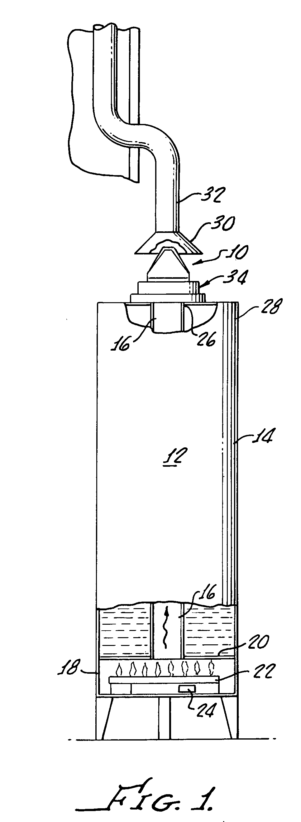
Turning now to FIG. 1, apparatus 10 in accordance with the present invention is shown, as installed on a hot water heater 12 having a tank 14, with a flue 16 therethrough and a combustion chamber 18 disposed at a bottom 20 of the tank 14 and water heater 12, the combustion chamber 18 having a conventional burner 22 and pilot light 24 disposed therein.

The apparatus 10 is designed to stop, limit or restrict flow of ambient air into a port 26 of the flue 16 and to conserve heat therein. The apparatus 10 is structured to be connected between an upper end 28 of the water heater 12 and a hood 30 of an exhaust flue 32.

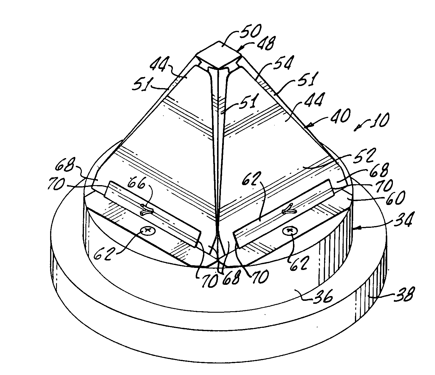
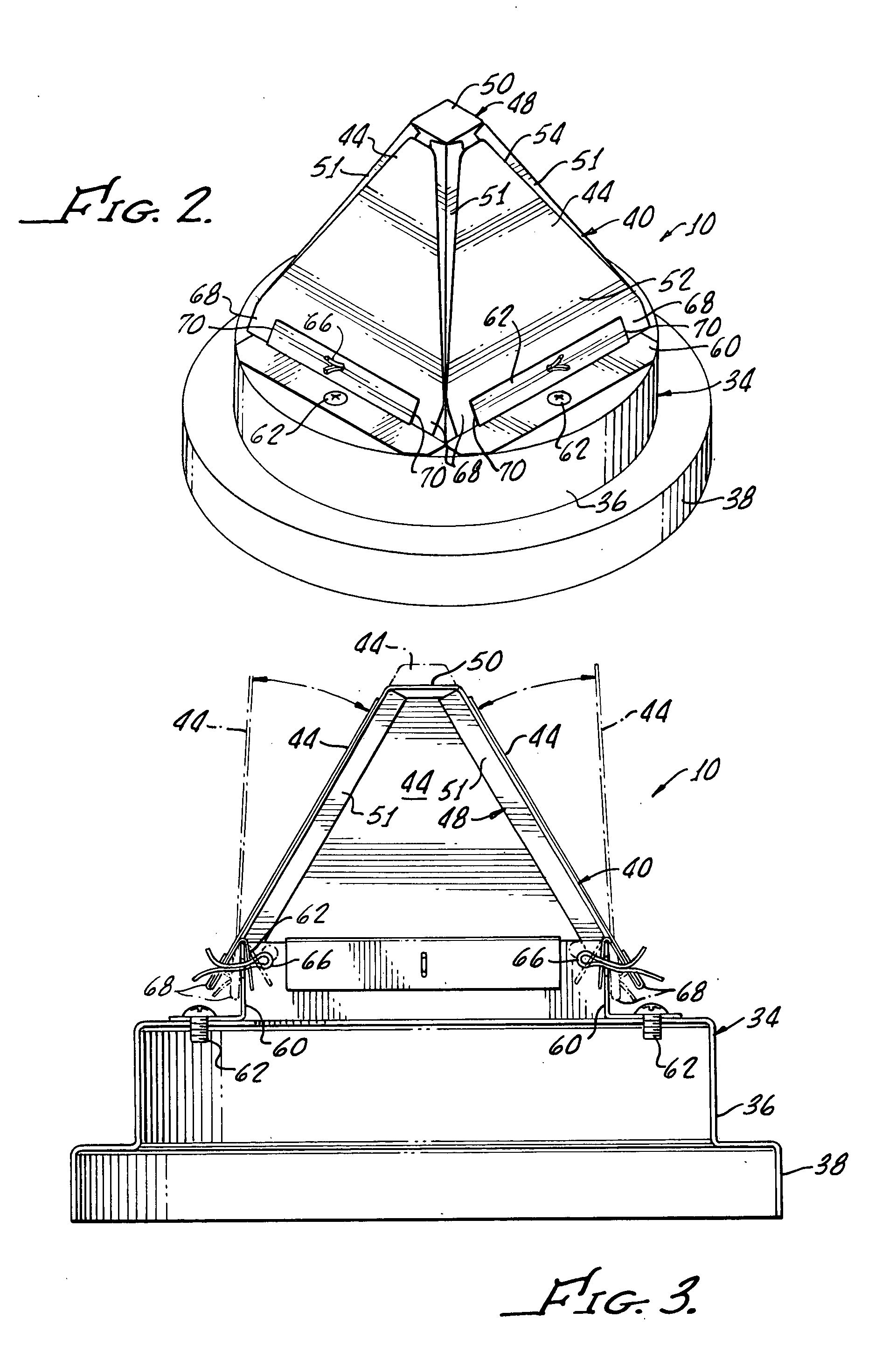
The apparatus 10 generally comprises a base 34 for connecting the apparatus 10 to the water tank 12 such that the apparatus 10 is disposed directly above the water heater flue 16 as shown.

It should be appreciated that the tank 14, burner 22, and water heater flue 16 may be of any conventional, suitable design. The base 34 of the apparatus 10 may be suitably structured to ...


PUM


Abstract

A vent damper apparatus provided for limiting flow of ambient air in a flue of a water heater. The apparatus generally includes a base structured to be connected to a water heater, and a damper assembly, extending from the base and structured to be responsive to a variable flow of exhaust gasses passing from a flue of the water heater. The damper assembly includes a plurality of independently movable dampers, and a frame structured to provide support to the plurality of independently movable dampers.

Description

The present invention generally relates to water heating apparatus and more specifically relates to vent damper apparatus for a water heater tank. Combustion hot water heaters typically utilize oil or natural gas which is burned in a combustion chamber disposed in a base of a hot water tank. Water heating is effected through the base of the hot water tank and additionally, through a central passageway, or exhaust flue, passing through the hot water tank. Exhaust gasses from the combustion chamber are vented through the flue and eventually are passed to the outside air, for example, by means of an exhaust port disposed above the water heater tank. Energy losses through an exhaust flue can be significant; it is estimated that approximately 33% of the heat energy generated from the main burner and pilot light operation is lost directly up the flue. In addition, an unrestricted duct allows cool room air to circulate freely through the hot water heater and its central core, thereby cooli...

Claims


Application Information

Patent Timeline
IPC IPC(8): F23L13/00F23L13/02F23L11/00F24H1/20
CPCF23L11/005F23L13/02F24H1/205
Inventor SCHIMMEYER, WERNER
Owner SCHIMMEYER WERNER
Why Eureka
Try Eureka