
Core setter for matchplate moulding machine

a technology of match plate and setter, which is applied in the field of moulding machines, can solve the problems of complex linkage mechanism, high force requirements, and difficult to meet these criteria with the known core-setting machine, and achieve the effect of reducing the bending of the holder and increasing the stiffness of the construction

Inactive Publication Date: 2005-03-22
DISA IND
View PDF7 Cites 10 Cited by
  • Summary
  • Abstract
  • Description
  • Claims
  • Application Information

AI Technical Summary

Benefits of technology

By using the drag flask to execute the vertical movement of the mould towards the core mask, the construction of the guiding mechanism for swinging the mask between a core-loading position and a core-releasing position can be significantly simplified. This results in a stiffer and more precise guiding mechanism.
According to another embodiment, the stiffness of the construction may be further increased by comprising points of support in the form of braces fixed to the base frame which give support in a vertical direction and which come in contact with the holder when it is in the core-releasing position for reducing bending of the holder when the cores are pressed into the mould.

Problems solved by technology

Core placing must, however, be precise and requires relatively high forces for pressing the cores into the mould cavities.
Moreover, the forces must not deform the construction since this could lead to core fracturing.
It is very difficult to fulfil these criteria with the complex linkage mechanism of the known core-setting machine.

Method used


Image

  • Core setter for matchplate moulding machine
  • Core setter for matchplate moulding machine
  • Core setter for matchplate moulding machine

Examples


Embodiment Construction

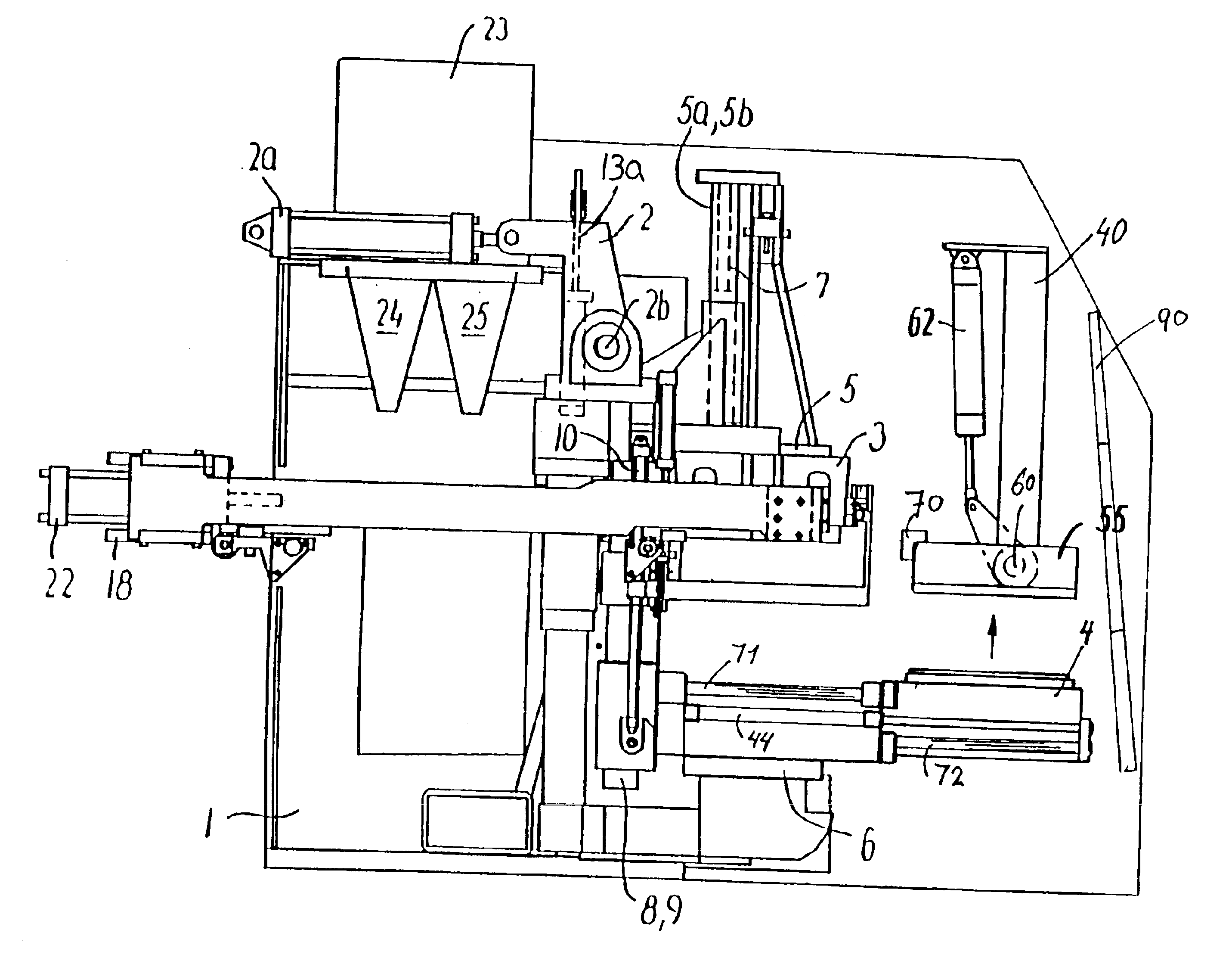
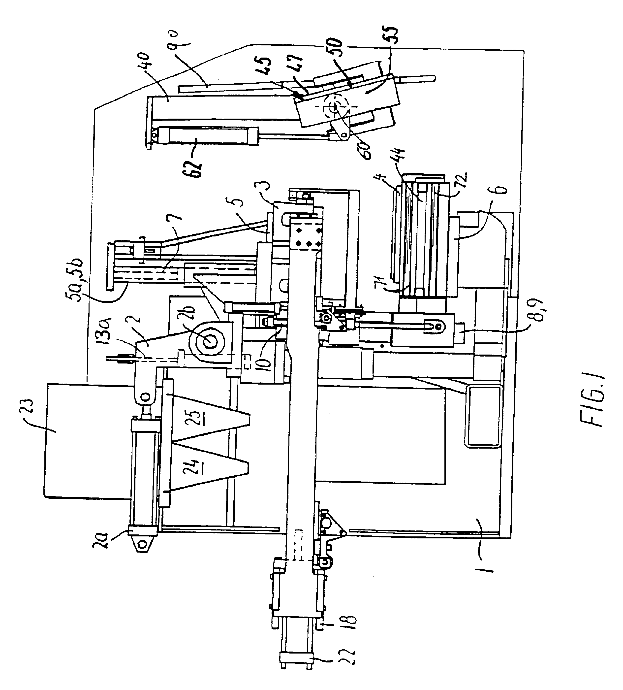
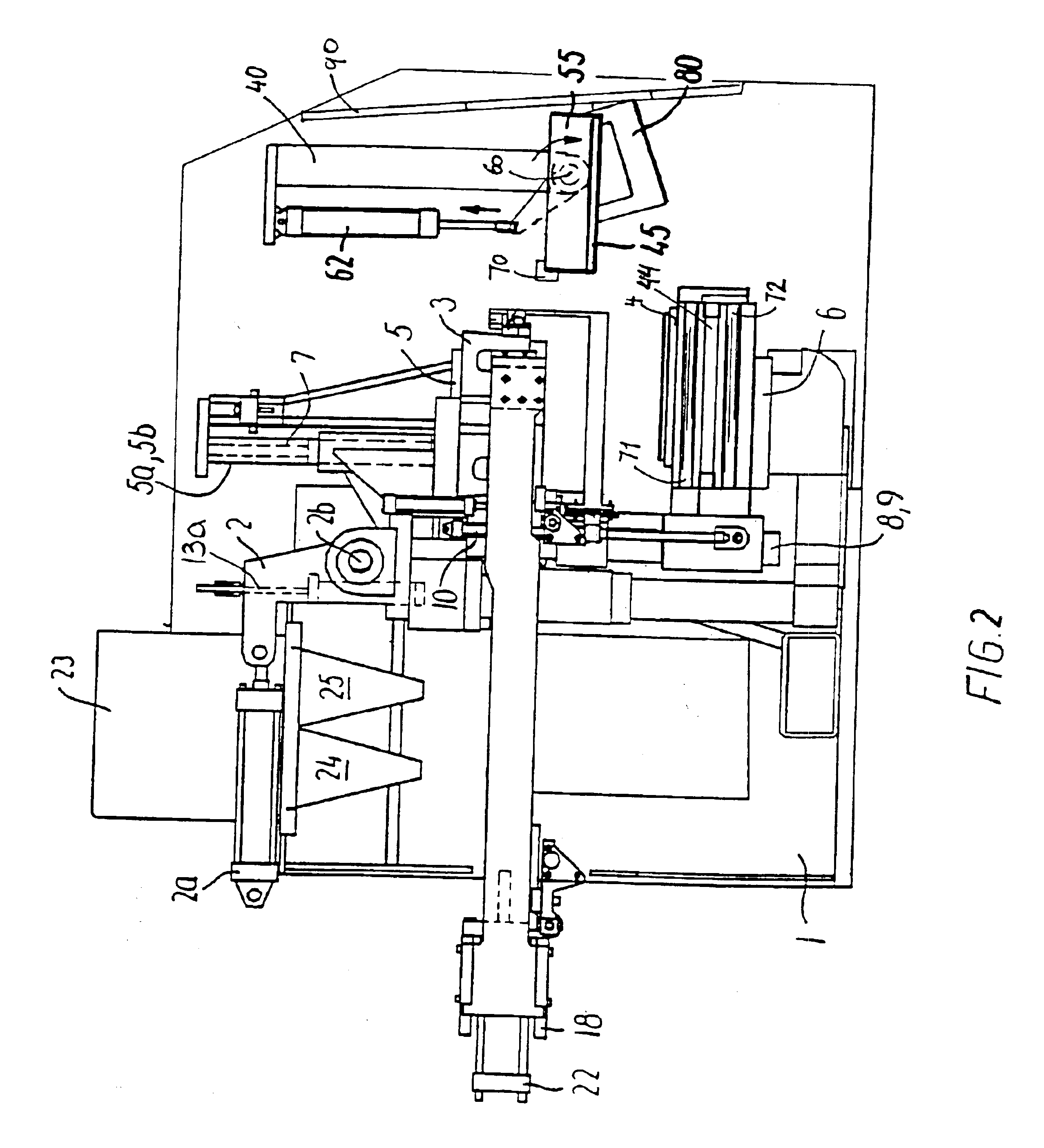
The moulding machine shown in FIGS. 1 to 9 is provided with a base frame 1 which carries the other components of the machine. A swing frame 2 is rotatably mounted to the base frame 1 through a shaft 2b, the swing frame 2 can be rotated by a hydraulic cylinder 2a. The swing frame 2 supports the cope flask 3 and the drag flask 4 as well as the first squeeze plate 5 and the second squeeze plate 6.

The cope flask 3 is fixed on the swing frame 2. The first squeeze plate 5 is suspended by two guide rods 5a, 5b from the swing frame. The upper ends of the guide rods 5a, 5b are connected to one another by a bracket 33. A hydraulic actuator 7 enables the first squeeze plate to be moved up and down. The first squeeze plate 5 is movably fitted in the cope flask 3.

A drag flask 4 is disposed below the cope flask 3. The drag flask 4 is suspended from the swing frame 2 by a pair of guide rods 8, 9 to allow a linear movement with respect to the latter. Two hydraulic actuators 10 are fastened with one...


PUM

PropertyMeasurementUnit
Angleaaaaaaaaaa
Angleaaaaaaaaaa
Areaaaaaaaaaaa

Abstract

A molding machine for providing flaskless molds comprising a drag flask (4) and a cope flask (3) is provided with a core setter (40) for placing cores in upwardly facing cavities of a mold located in the drag flask (4). The core setter (40) comprises a core mask (45) with pockets (49) selectively operable to hold and release cores (50), said core mask being supported by a holder (55) that is pivotally journalled around a horizontal axis to swing between a core-releasing position and a core-loading position. The core mask (45) faces downwardly towards the mold when it is in the core-releasing position and faces laterally away from said mold when it is in the core-loading position. The drag flask (4) is arranged to be movable in a substantially horizontal direction to and from a core-setting position directly under the core mask (45) in its core-releasing position. The drag flask (4) is arranged to be movable upwards to and downwards from the core mask (45) when it is in the core-setting position. When the core mask (4) has been loaded with the cores (50), it is swung to the core-releasing position. The drag flask (4) is then moved from its position under the core mask (45). The drag flask (4) is then moved up towards the core mask (45) and the cores (50) are pressed into the cavities (49) in the mold. The cores (50) are then released by the core setter (40) and the drag flask (4) moves back to its position under the cope flask (3).

Description

TECHNICAL FIELDThe present invention relates to a moulding machine for producing flaskless moulds which is provided with means for automatically placing cores in the cavities of sand moulds produced by the moulding machine.BACKGROUND ARTAn automatic core setting machine is disclosed in U.S. Pat. No. 4,590,982. In that machine the cores are carried in pockets in a mask which places the cores in the cavities of the moulds. Typically the cores are held by vacuum. The apparatus is suited for placing cores in moulds that have upwardly opening mould cavities. Hereto the core mask is swung downwardly and laterally through a short arc from a core-loading position to a pre-setting position and then is lowered vertically to a core-releasing position to place the cores in the mould. When the mask is in its loading position, its pockets face away from the mould station to enable the cores to be loaded in the pockets from the side of the machine. In order to carry out the combined rotational, la...

Claims


Application Information

Patent Timeline
IPC IPC(8): B22C11/00B22C11/10B22C9/10
CPCB22C11/10B22C9/108
Inventor KNUDSEN, S.O SLASHED.REN ERIK
Owner DISA IND
Learn More