Tubular cutting tool

a cutting tool and tube technology, applied in the direction of driving apparatus, fluid removal, earthwork drilling and mining, etc., can solve the problems of preventing the use of devices in this category, and affecting the operation of the devi

Inactive Publication Date: 2005-03-22
SONDEX
View PDF16 Cites 67 Cited by
  • Summary
  • Abstract
  • Description
  • Claims
  • Application Information

AI Technical Summary

Benefits of technology

The present invention overcomes the difficulties encountered in the prior art by providing a tubular cutting tool which can be deployed on a single cable with a small crane and winch unit to produce a clean cut end, reminiscent of a machined edge, by incorporating both an electrically actuated anchoring mechanism capable of compensating for variations in the internal radii of the tubular to be cut, thereby ensuring that the cutting tool device is clamped rigidly in position, and an electrically driven rotary cutting head having a single, small sharp cutting blade.

Problems solved by technology

These devices suffer from logistical and operational difficulties and impediments arising from the additional safety precautions required when utilising explosives and corrosive chemicals.
Such devices suffer from the disadvantage of being cumbersome, as well as expensive to purchase, deploy and operate; the operation and deployment of the devices commonly requires a complete drill rig.
Furthermore, in situations where the tubular to be cut is narrow employment of devices in this category may be precluded.
Gouging a cut through the tubular, rather than performing a precision cut, suffers from the disadvantage of requiring a large amount of energy as well as producing long “apple peel” spirals of metal which can fall into the tubular and hinder the cutting operation as well as future operations on the cut tubular.
In general, even tubular cutting tools incorporating more than one blade to perform a precision cut, rather than gouging a cut, suffer from the disadvantage that multiple blades have a tendency to “skip” in and out of the individual cuts they produce, resulting in an increased propensity for the blades to snap; in a single bladed tool, the single cutting blade runs around the wall of the tubular in its own cut, even in a slight eccentric or angled deployment.
In addition to the disadvantages already discussed, devices in both categories typically leave the cut end of the tubular in a ragged condition, which can occlude subsequent operations involving the tubular.
The use of hydraulic and / or pneumatic means results in the devices requiring multiple cables / hoses which can lead to additional deployment problems when the device is to be used in a tubular, for example, a live oil well, having a seal and airlock mechanism and / or when a cut is to be made at great depth.

Method used


Image

  • Tubular cutting tool
  • Tubular cutting tool
  • Tubular cutting tool

Examples


Embodiment Construction

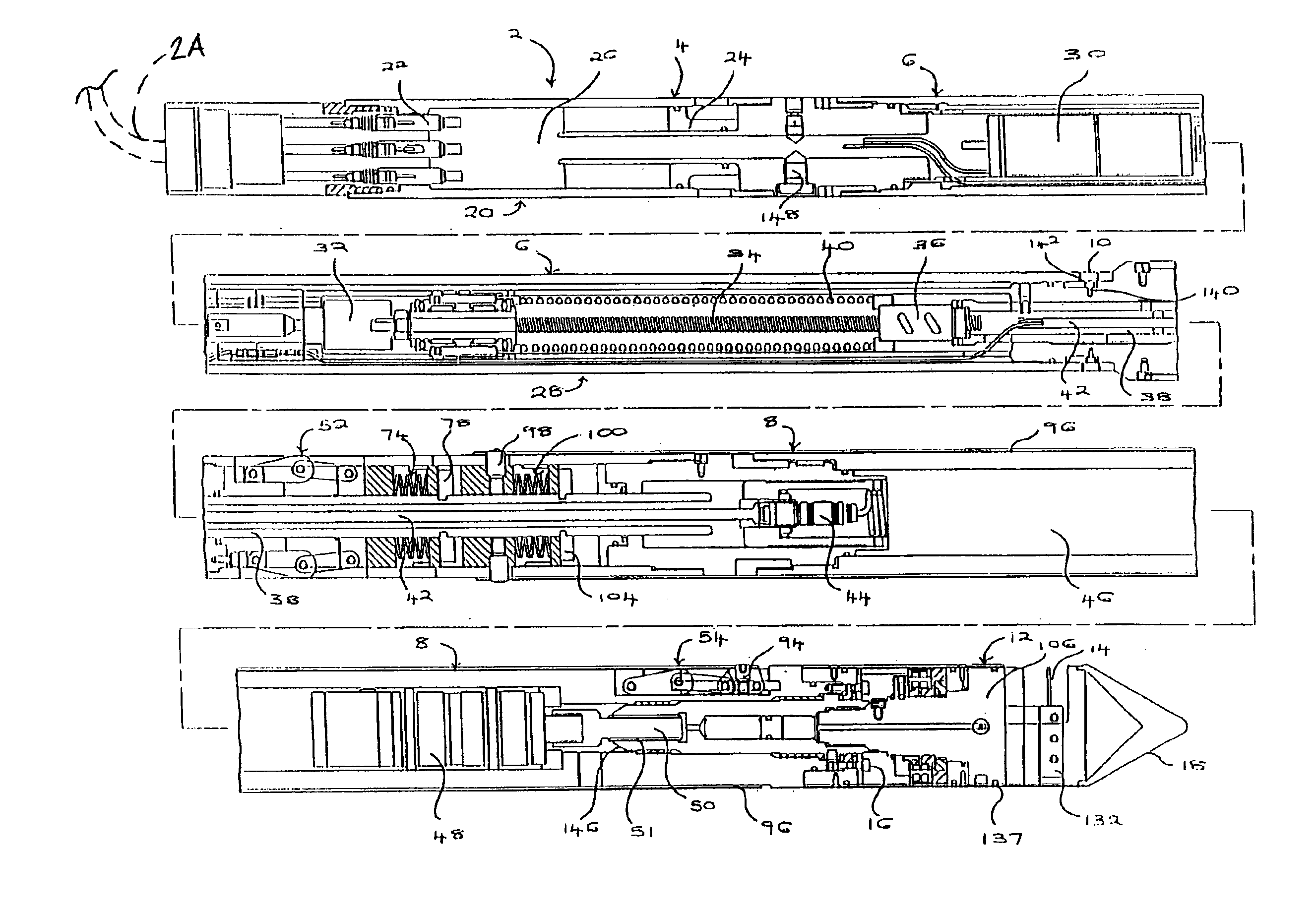
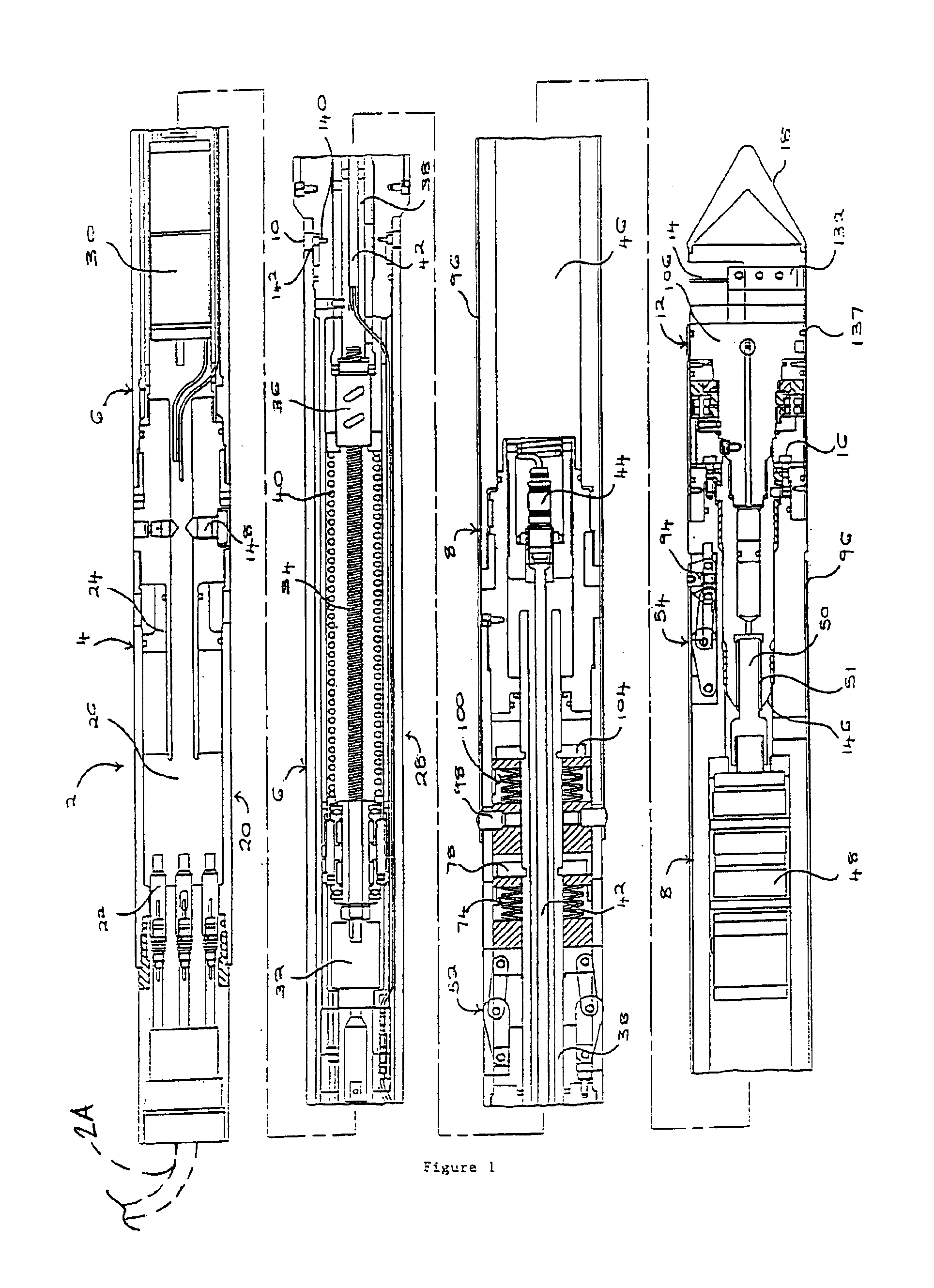
The preferred tubular cutting tool 2 illustrated in FIG. 1, has a cylindrical housing 4, having an upper housing section 6 to the top of the Figure and a lower housing section 8 to the bottom of the Figure. The upper and lower housing sections are locked together by weakened linking pins 10. An electrically driven rotary cutting head 12 having a retractable cutting blade 14 is mounted on the end of the lower housing section 8 distant from the upper housing section 6. The electrically driven rotary cutting head 12 is locked to the lower housing section 8 by weakened linking pins 16. The end of the electrically driven rotary cutting head 12 distant to the lower housing section 8 has a tapered nose cone 18.

A deployment cable and an interface electronics cartridge, are attached to the upper end of the upper housing section 6, distant to the lower housing section 8; for simplicity the electronics cartridge and deployment cable have been omitted from the FIGS.. The upper end portion 20 of...


PUM

PropertyMeasurementUnit
internal diametersaaaaaaaaaa

Abstract

A tubular cutting tool includes two or more sets of electrically actuated retractable anchoring legs mounted at longitudinally spaced apart locations and an electrically driven rotary cutting head with a retractable cutting blade. The anchoring legs can be arranged such that they are capable of compensating for variations in the internal radii of the tubular to be cut, thereby ensuring that the cutting tool is clamped rigidly in position.

Description

BACKGROUND OF THE INVENTIONThis invention relates to a tubular cutting tool, namely a device for remotely cutting tubulars, such as well casings, drill pipes and underwater or buried pipes, from the inside, using an electrically driven cutting head.During certain phases of well drilling and development it is necessary to recover metal tubulars, or sections thereof, from the borehole. In order to achieve this, a device must be lowered inside the tubular, then operated remotely to perform a cut. The devices commonly employed in the art for this purpose can be largely divided into two categories.The first category encompasses explosive or “chemical cutting” devices which are deployed on a cable, wireline or electric line. Examples of such devices are described in U.S. Pat. Nos. 5,129,322 and 4,125,161. These devices suffer from logistical and operational difficulties and impediments arising from the additional safety precautions required when utilising explosives and corrosive chemical...

Claims


Application Information

Patent Timeline
Patent Type & Authority Patents(United States)
IPC IPC(8): E21B29/00E21B23/00E21B23/01
CPCE21B23/01E21B29/005Y10T409/304424
Inventor MASON, GUY HARVEYSTUART-BRUGES, WILLIAM PETERSEARIGHT, THOMAS LEMPRIERESTRONG, PHILIP ANTONBOXELL, TIMOTHY GEORGEYURATICH, MICHAEL ANDREWFRASER, ALAN THOMAS
Owner SONDEX
Why Eureka
Try Eureka