Receptacle for grinder tools

Inactive Publication Date: 2005-03-22
ROBERT BOSCH GMBH +1
View PDF28 Cites 71 Cited by
  • Summary
  • Abstract
  • Description
  • Claims
  • Application Information

AI Technical Summary

Benefits of technology

If at least one detent element is integrally-moulded to a discoid component and/or if at least two elements for immobilizing the application tool in the axial direction are integrally-moulded to a d

Problems solved by technology

The application tool can be reliably prevented from spinning off, even when th

Method used


Image

  • Receptacle for grinder tools
  • Receptacle for grinder tools
  • Receptacle for grinder tools

Examples


Example

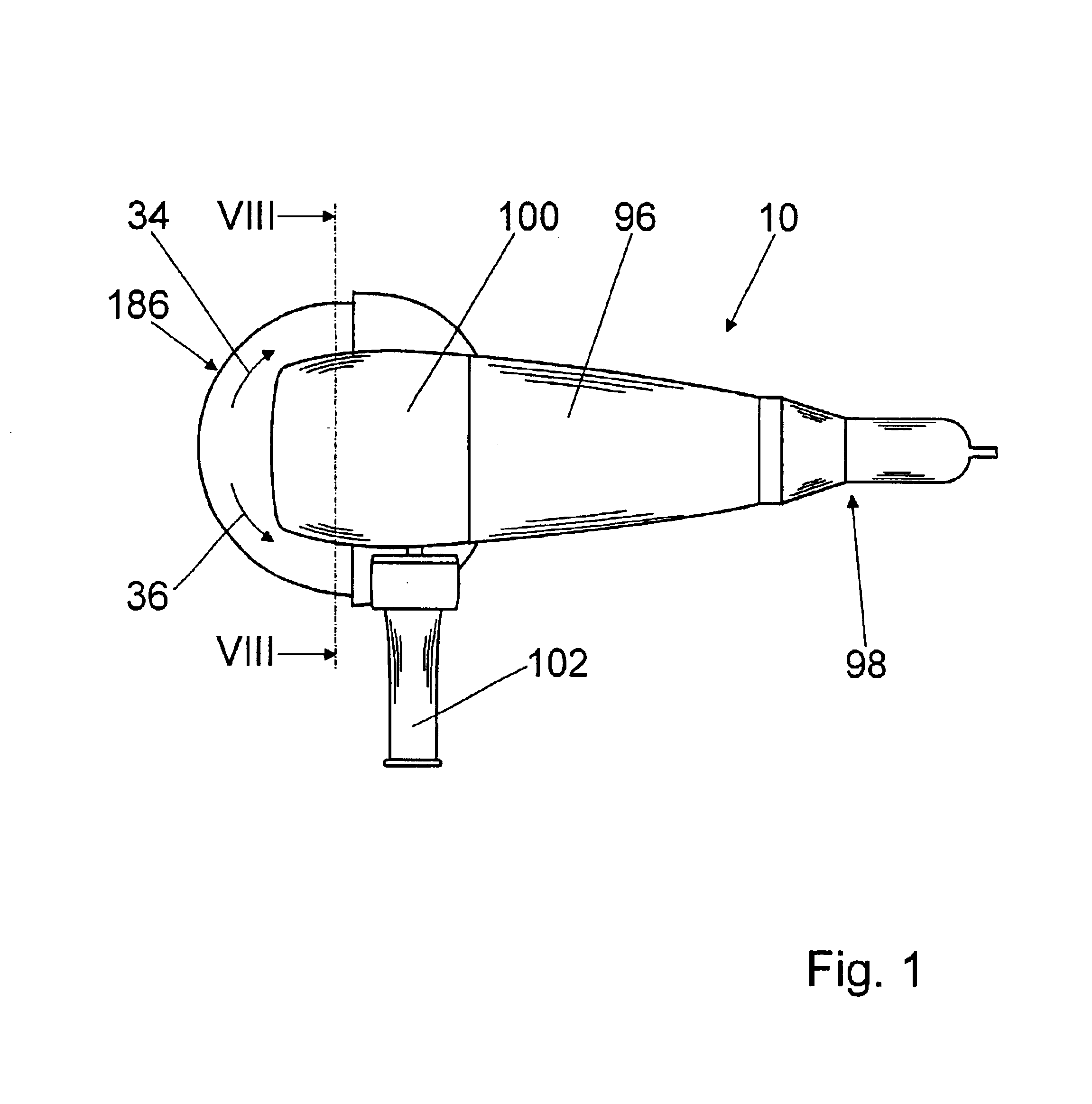
FIG. 1 shows an angle grinder 10 from above having an electric motor—not shown in greater detail—located in a housing 96. The angle grinder 10 can be guided via a first handle 98 extending in the longitudinal direction and integrated in the housing 96 opposite to a cutoff wheel 18 and via a second handle 102 extending at an angle to the longitudinal direction secured to a drive housing 100 in the vicinity of the cutoff wheel 186.

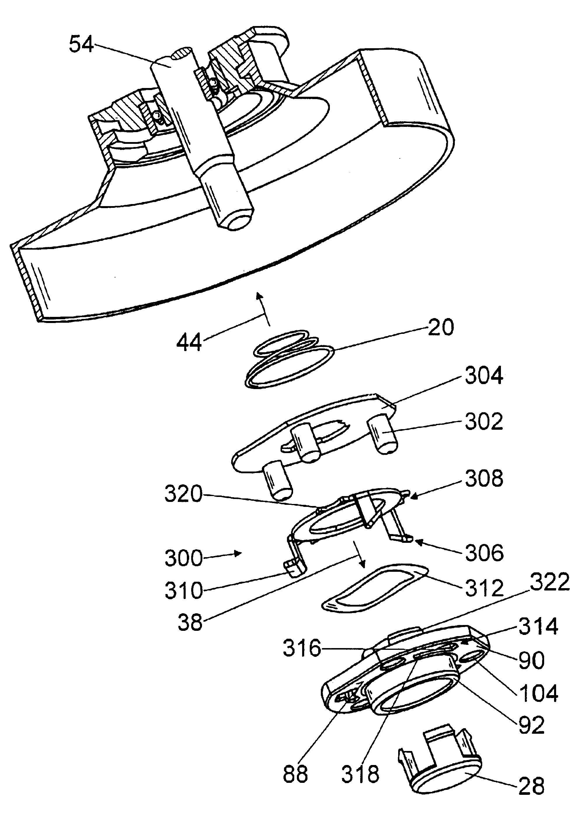
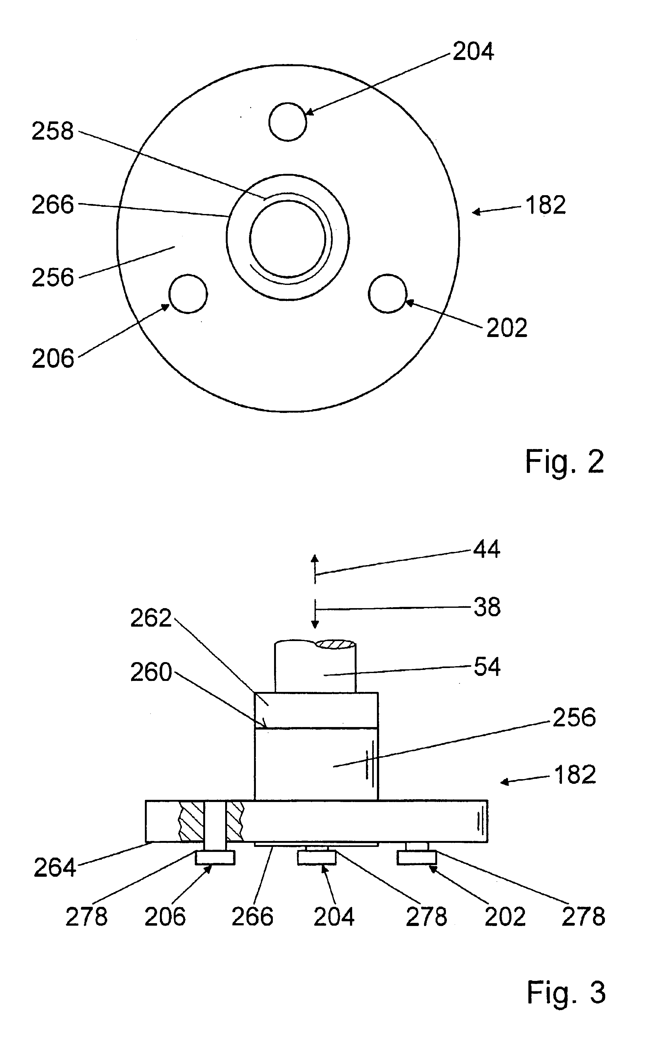
Using the electric motor, a drive shaft 54 can be driven via a gear mechanism, not shown in greater detail, on its end pointing toward the cutoff wheel 186 of which a carrier device 182 is located (FIGS. 2 and 3).

The carrier device 182 comprises a driving flange 256. The driving flange 256 is screwed into place on the drive shaft 54 via a thread 258 and, with a face 260 pointing in the direction 44 opposite to the cutoff wheel 186, extends to a collar 262 on the drive shaft 54. It would also be possible to connect a driving flange with a drive shaft in non-d...


PUM


Abstract

The invention is based on a tool receiver for a grinder, in particular for a handheld angle grinder (10), having a carrier device (12, 14, 16, 182, 184, 300), via which an application tool (18, 32, 186, 188) can be actively connected to a drive shaft (54).
It is proposed that the application tool (18, 32, 186, 188) be actively connectable to the carrier device (14, 16, 182, 184) via at least one detent element (24, 26, 190, 192, 194, 196, 198, 200, 302) movable against a spring force that snaps into place in an operating position of the application tool (18, 32, 186, 188) and immobilizes the application tool (18, 32, 186, 188) with positive engagement.

Description

BACKGROUND OF THE INVENTIONThe invention is based on a tool for a grinder.A tool receiver for a grinder for a handheld angle grinder is made known in EP 0 904 896 A2. The angle grinder comprises a drive shaft that carries a thread on the tool side.The tool receiver for a grinder comprises a carrier and a tensioning nut. To install a sanding disk, the carrier with an installation opening is pushed onto a collar of the drive shaft and tightened with positive engagement against a bearing surface via the tensioning nut. The carrier has a collar extending in the axial direction on the tool side that comprises radially-situated recesses on two opposite sides on its outer circumference that extend in the axial direction to a base of the collar. Starting at the recesses, one groove each extends around the outer circumference of the collar against the driving direction of the drive shaft. The grooves are closed against the driving direction of the drive shaft and taper axially starting at th...

Claims


Application Information

Patent Timeline
IPC IPC(8): B24D9/00B24D7/00B24D9/08B24D7/16B24B23/02B24B23/00B24B45/00
CPCB24B23/02B24D9/085B24D7/16B24B45/006
Inventor WENDT, DIETERKRONDORFER, HARALDDAMMERTZ, RALPHHECKMANN, MARKUSSCHADOW, JOACHIMSCHOMISCH, THOMASBRANCATO, MARCOHOELZL, CHRISTOFHUBER, JOHANNSCHULZE, WILHELM
Owner ROBERT BOSCH GMBH
Why Eureka
Try Eureka