Ophthalmologic photocoagulator and photocoagulation method thereof

a technology of ophthalmologic photocoagulator and photocoagulation method, which is applied in the field of ophthalmologic photocoagulator, can solve the problems of inability to conduct high-precision sighting of the diseased part, inability to accurately detect the diseased part, and inability to increase the size of the conventional ophthalmologic photocoagulator

Inactive Publication Date: 2005-03-22
KK TOPCON
View PDF9 Cites 10 Cited by
  • Summary
  • Abstract
  • Description
  • Claims
  • Application Information

AI Technical Summary

Problems solved by technology

However, increase in the size of the conventional ophthalmologic photocoagulator is inevitable, causing a problem in view of spaces of a treatment room and an operating room.
However, the following problems are generated in the conventional ophthalmologic photocoagulators.
That is, when the eye fundus having a color similar to the red sighting laser beam is spotted with the red sighting laser beam, the visibility thereof is bad.
Therefore, it is difficult to conduct sighting on the diseased part with high precision.
In addition, when the dichroic mirror is used as the combining means for combining the optical path of the treatment laser beam with the optical path of the sighting laser beam, a loss in the amount of any one of the laser beams that is transmitted through the combining means has to become large (about 7%).
This becomes one of factors limiting the degree of freedom in design of an apparatus.

Method used


Image

  • Ophthalmologic photocoagulator and photocoagulation method thereof
  • Ophthalmologic photocoagulator and photocoagulation method thereof

Examples


first embodiment

Structure of Ophthalmologic Photocoagulator

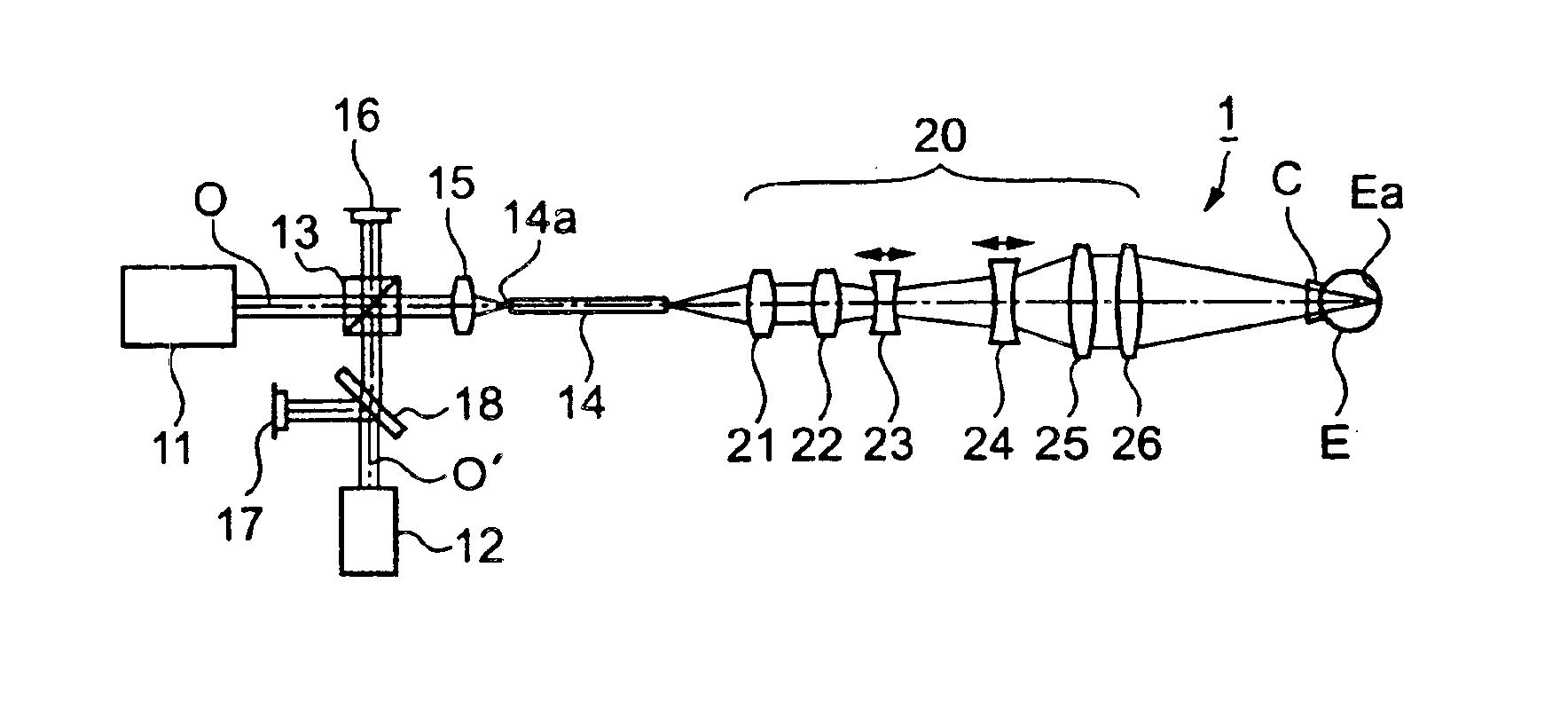
FIG. 1 is a schematic view showing an optical structure of an ophthalmologic photocoagulator 1 according a first embodiment of the present invention. The ophthalmologic photocoagulator 1 includes a treatment laser oscillator 11, a sighting laser oscillator 12, a polarization beam splitter 13, an optical fiber 14, a condenser lens 15, photo diodes 16 and 17, a glass plate 18, and a laser irradiation optical system 20.

The ophthalmologic photocoagulator 1 is provided with the two laser oscillators. The treatment laser oscillator 11 is a treatment laser oscillating means that oscillates treatment laser beam for conducting treatment to a diseased part on an eye fundus Ea of an eye to be examined E by photocoagulation. Further, the sighting laser oscillator 12 composes a sighting laser oscillating means that oscillates sighting laser beam for conducting sighting on the diseased part to be irradiated with the treatment laser beam.

The treatment las...

second embodiment

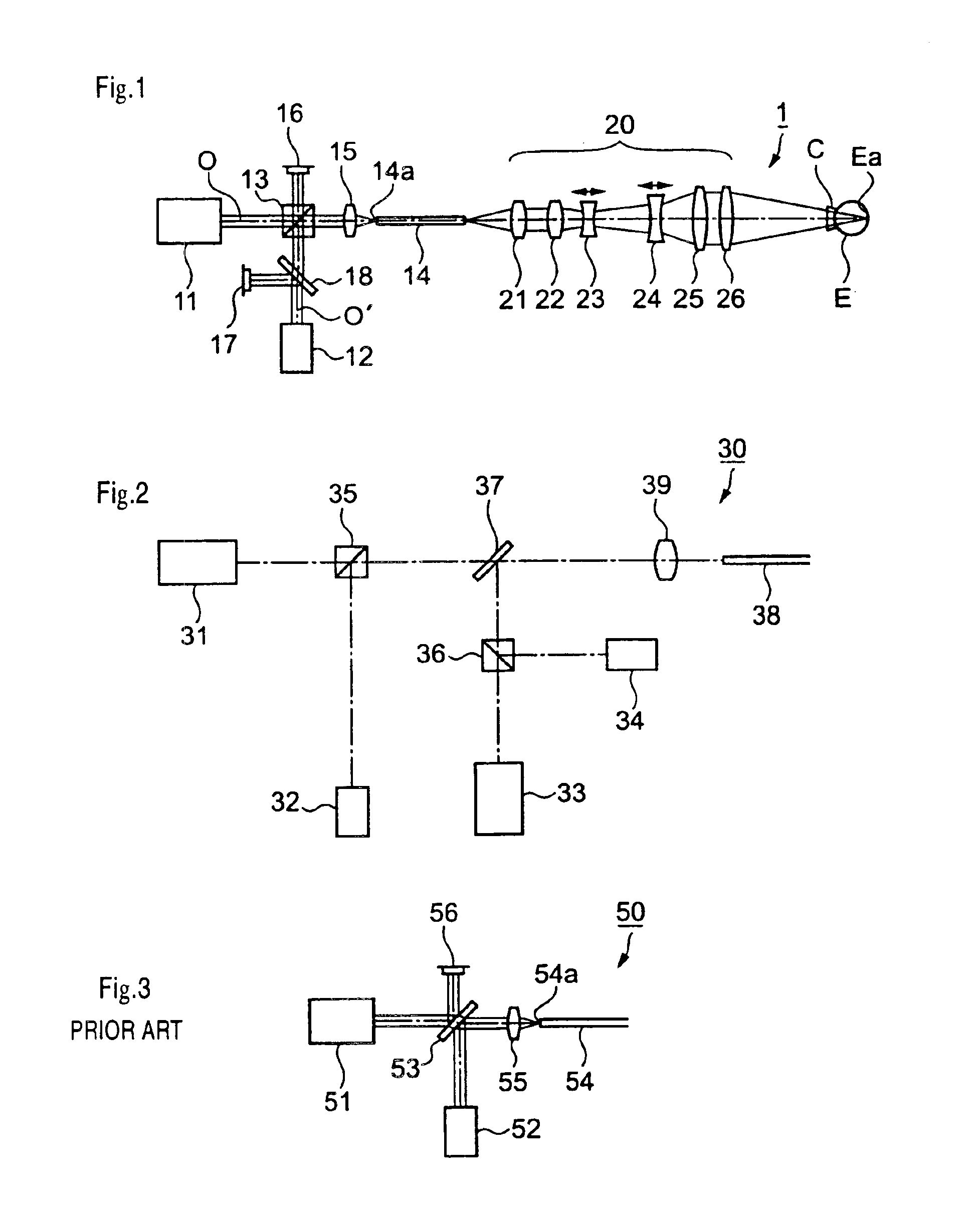
FIG. 2 is a schematic view showing an optical structure of an ophthalmologic photocoagulator 30 according to a second embodiment of the present invention. The ophthalmologic photocoagulator 30 is an apparatus for conducting treatment by photocoagulation using laser beams of plural colors and includes treatment laser oscillators 31 and 33, sighting laser oscillators 32 and 34, polarization beam splitters 35 and 36, a dichroic mirror 37, an optical fiber 38, and a condenser lens 39. It is possible that photo diodes are provided as in the ophthalmologic photocoagulator 1 of the first embodiment and feedback for output control is conducted. Note that laser beam incident into the optical fiber 38 is guided to a slit lamp to irradiate an eye to be examined. Because such operation is similar to that in the case of the ophthalmologic photocoagulator 1, the detailed description thereof is referred to the same case.

The treatment laser oscillators 31 and 33 oscillate treatment laser beams havi...


PUM


Abstract

An ophthalmologic photocoagulator and photoagulation method thereof in which visibility of sighting laser beam which is projected onto the eye fundus of an eye to be examined is improved and a loss in the amount of treatment laser beam can be reduced. The ophthalmologic photocoagulator includes: a treatment laser oscillator that oscillates a treatment laser beam for conducting treatment on a diseased part of the eye to be examined by photocoagulation; a sighting laser oscillator that oscillates a sighting laser beam for conducting sighting on the diseased part of the eye to be examined which is to be irradiated with the treatment laser beam; and a polarization beam splitter for combining an optical path of the treatment laser beam with an optical path of the sighting laser beam by polarization coupling. The treatment laser beam oscillating from the treatment laser oscillator and the sighting laser beam oscillating from the sighting laser oscillator have similar colors.

Description

BACKGROUND OF THE INVENTION1. Field of the InventionThe present invention relates to an ophthalmologic photocoagulator that conducts treatment on a diseased part of an eye to be examined by photocoagulation.2. Description of the Related ArtUp to now, an ophthalmologic photocoagulator of a water cooling type, which is capable of continuously oscillating laser beam, has been a mainstream of the conventional ophthalmologic photocoagulator. Such an ophthalmologic photocoagulator is provided with a single laser oscillator, and uses treatment laser beam and sighting laser beam separately by inserting and removing a dense filter into and from an optical path of the laser beam. However, increase in the size of the conventional ophthalmologic photocoagulator is inevitable, causing a problem in view of spaces of a treatment room and an operating room. Note that the treatment laser beam means laser beam applied for conducting treatment on a diseased part of an eye to be examined by photocoagul...

Claims


Application Information

Patent Timeline
Patent Type & Authority Patents(United States)
IPC IPC(8): A61F9/01A61F9/007
CPCA61F9/00821A61F2009/00872A61F2009/00863A61F2009/00844
Inventor SAGEHASHI, HIDEOOOYAGI, WATARUMOMIUCHI, MASAYUKI
Owner KK TOPCON
Why Eureka
Try Eureka