Prosthesis

Active Publication Date: 2005-03-22
FINSBURY DEV
View PDF38 Cites 114 Cited by
  • Summary
  • Abstract
  • Description
  • Claims
  • Application Information

AI Technical Summary

Benefits of technology

The present invention accordingly seeks to provide a two part tibial prosthesis suitable for assembly by a surgeon prior to surgical implantation in a patient which will substantially avoid the risk of micro

Problems solved by technology

However, the existing clip mechanisms have the disadvantage that, since the tibia insert is merely clipped into place, there is room for motion since only the clip portion of the tibia insert resists such motion.
Thus, although the surgeon may feel the insert clip into place and it may seem that the insert is not moving easily, such mechanisms do in fact allow relative movement between the tray and insert when the prosthesis

Method used


Image

  • Prosthesis
  • Prosthesis
  • Prosthesis

Examples


Example

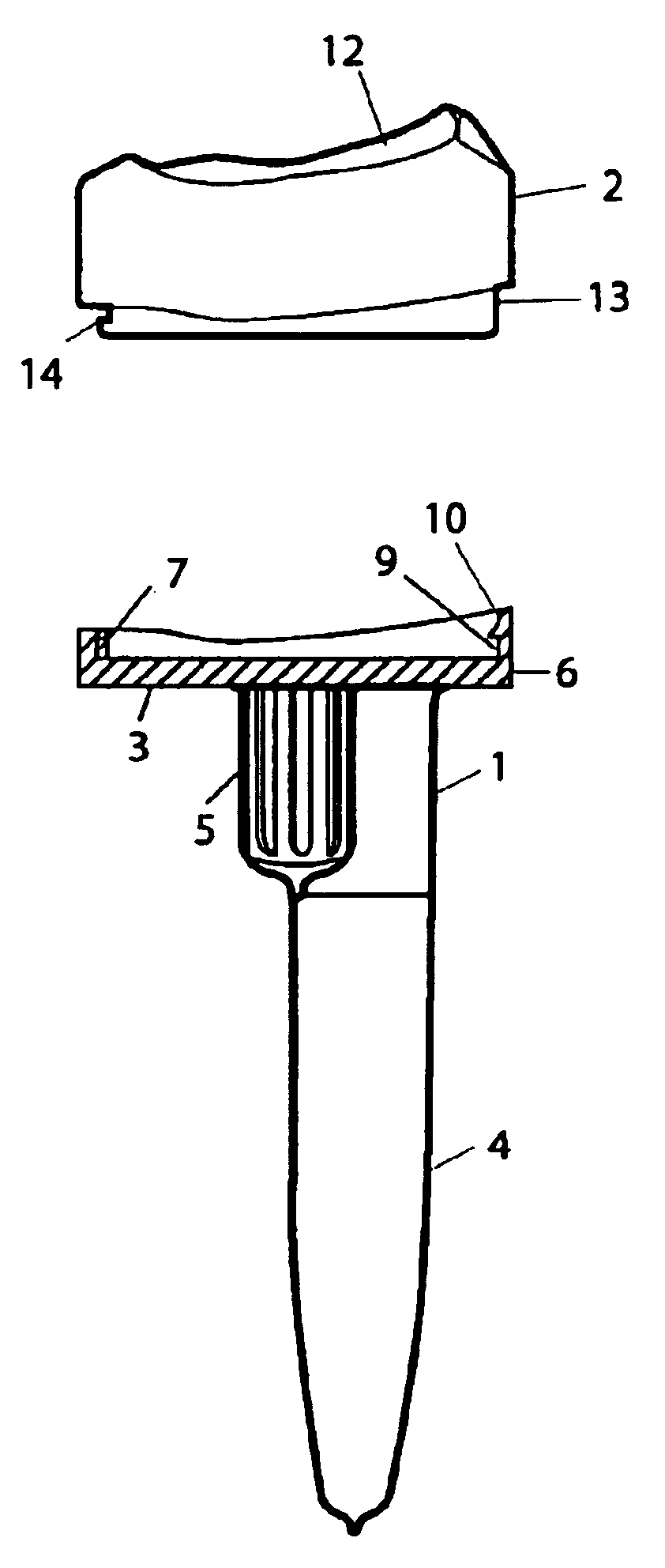
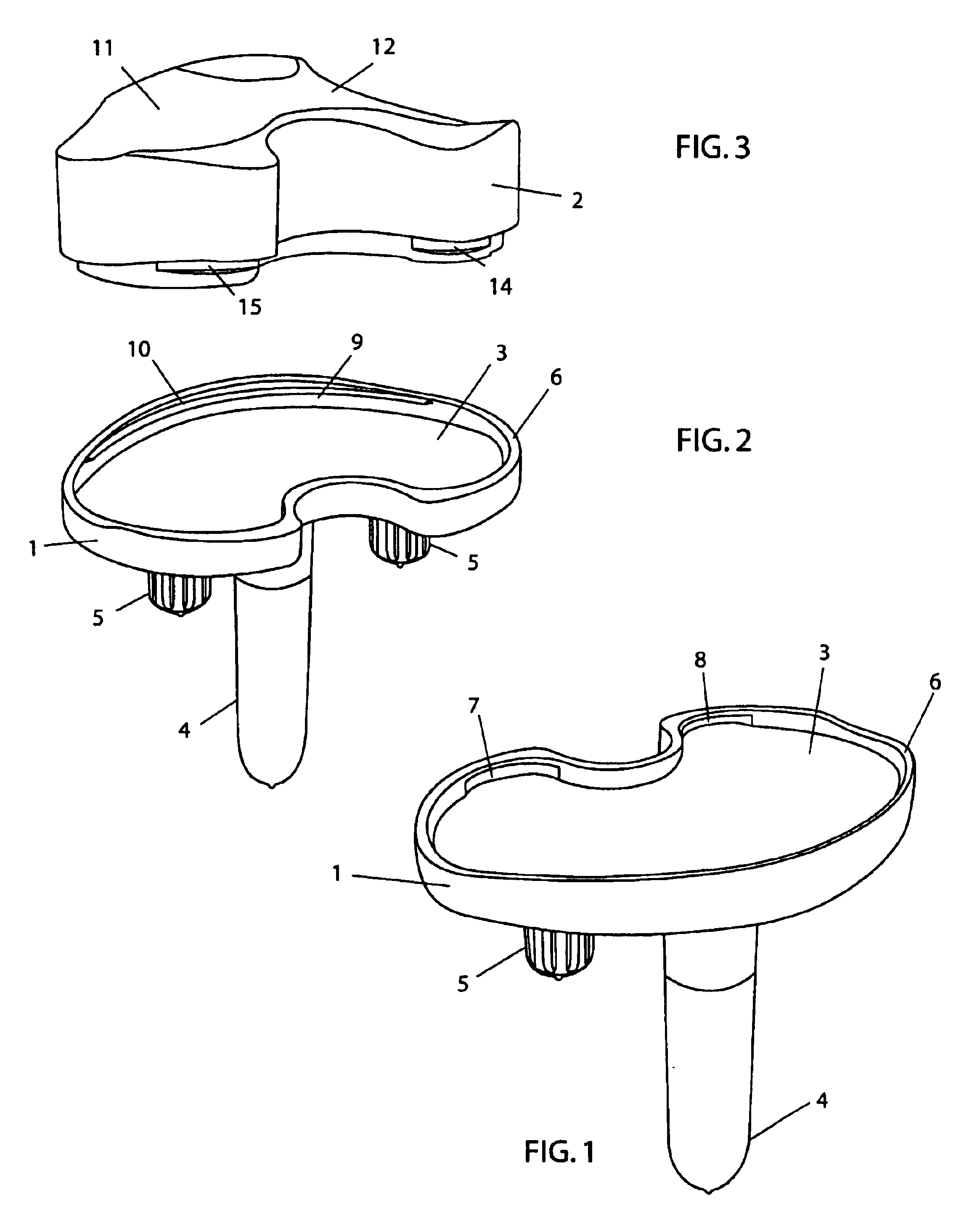
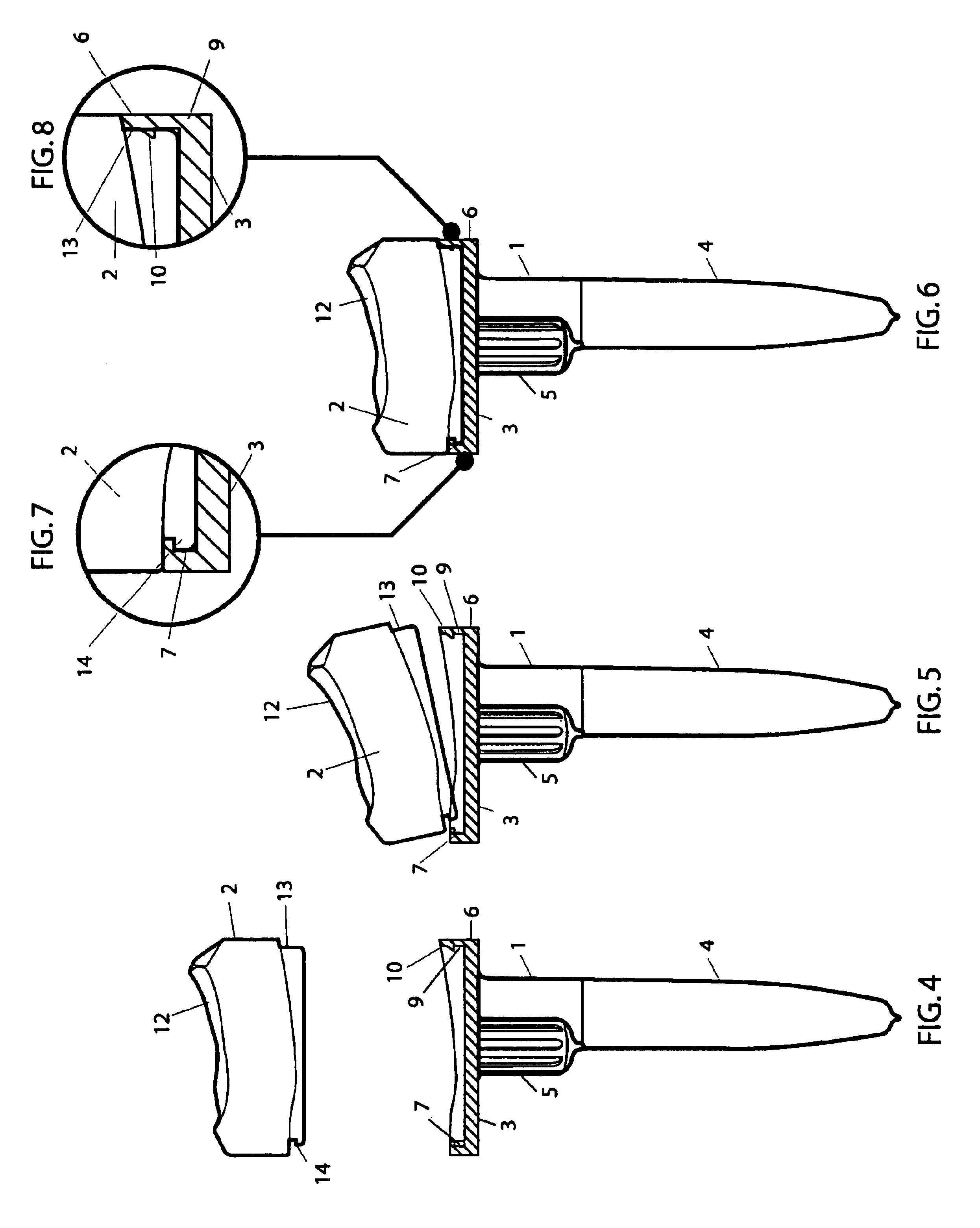
Referring to the drawings, and to FIGS. 1 to 3 in particular, a total tibial prosthesis according to the invention comprises a metal tray component 1, which is made from a suitable biocompatible metal or alloy, such as stainless steel, nickel-cobalt, titanium or a titanium alloy, and a tibia insert 2 made of a suitable plastics material, such as ultra high molecular weight polyethylene. Tray component 1 comprises a transverse member in the form of a generally flat plate 3 from the underside of which projects a stem 4 and two pegs 5. Stem 4 is intended for receipt in a surgically prepared cavity that extends substantially parallel to the axis of a tibia of a patient into whom the tibial prosthesis is to be implanted and is formed in a resected face of the tibia, while pegs 5 are intended for receipt in corresponding further smaller axial cavities in the resected tibia. Surrounding the plate 3 is a upstanding peripheral rim 6. The posterior portion of rim 6 is undercut in two places s...


PUM


Abstract

A tibial prosthesis has a metal tray component (1) comprising a transverse member (3) with a peripheral upstanding rim (6) and a projecting stem (4). The upstanding rim (6) includes a posterior rim portion with an undercut lip forming a pair of recesses (7, 8) and an anterior rim portion with an open angled posterior surface portion (9) and a posteriorly projecting barbed portion (10). The prosthesis also includes a tibia insert (2) made of a plastics material which fits on the tibial implant (1) within the upstanding rim (6) and has on a posterior portion thereof a shaped contour (14, 15) adapted in use to fit snugly under the undercut lip and on an anterior portion thereof an anterior surface (13) having a taper angle substantially corresponding to the angle of the open angled posterior surface portion.

Description

BACKGROUND OF THE INVENTIONThis invention relates to a tibial prosthesis for implantation in a surgically prepared cavity in a tibia of a patient undergoing knee replacement.Tibial prostheses are commonly made in two parts, namely a metal tray-shaped component with a stem projecting from a lower side thereof for insertion in a surgically prepared cavity in a tibia of a patient requiring a tibial surface replacement operation and with an upstanding peripheral rim and a tibia insert which is typically made from ultra high molecular weight polyethylene that fits on top of the tray component and is located in place inter alia, by means of the upstanding peripheral rim.There are typically 6 sizes of the metal tray-shaped component to account for variations in tibia bone size and 5 thicknesses of tibia insert to account for variation in the amount of bone resected and laxity of the collateral ligaments. Tibia inserts typically also come in 2 or 3 sizes to best fit the range of metal tray ...

Claims


Application Information

Patent Timeline
IPC IPC(8): A61F2/38
CPCA61F2/389
Inventor TUKE, MICHAEL ANTHONYWOZENCROFT, ROBERT MICHAELTAYLOR, ANDREW CLIVE
Owner FINSBURY DEV
Why Eureka
Try Eureka