Prosthetic joint component having multiple arcuate bending portions

a technology of prosthetic joints and arcuate bending, applied in the field of prosthetic joints, can solve the problems of unnatural position, potential failure of the pivot or hinge portion of the implant, and no angle between the opposing stems in their natural position, and achieve the effect of decreasing the overall stress on the devi

Inactive Publication Date: 2005-03-22
DEPUY ORTHOPAEDICS INC
View PDF17 Cites 51 Cited by
  • Summary
  • Abstract
  • Description
  • Claims
  • Application Information

AI Technical Summary

Benefits of technology

The present invention addresses the above needs, as well as others, by providing a joint prosthetic component that includes a joint member having a concavity that includes multiple arcuate portions. When the joint member is flexed, the joint member bends at each of the arcuate portions. As a result, the stresses and forces exerted during bending of the joint prosthetic component will not tend to be concentrated on a single bend spot or bend line. The concavity having multiple arcuate portions is preferably combined with another concavity on...

Problems solved by technology

One drawback to many of these devices is that they employ no angle between the opposing stems in their natural position (i.e. without force applied).
Such a position is unnatural as the natural “at-rest” posture of the phalanges is not a straight line.
One drawback to many prior art devices, including the Avanta PIP de...

Method used


Image

  • Prosthetic joint component having multiple arcuate bending portions
  • Prosthetic joint component having multiple arcuate bending portions
  • Prosthetic joint component having multiple arcuate bending portions

Examples


Embodiment Construction

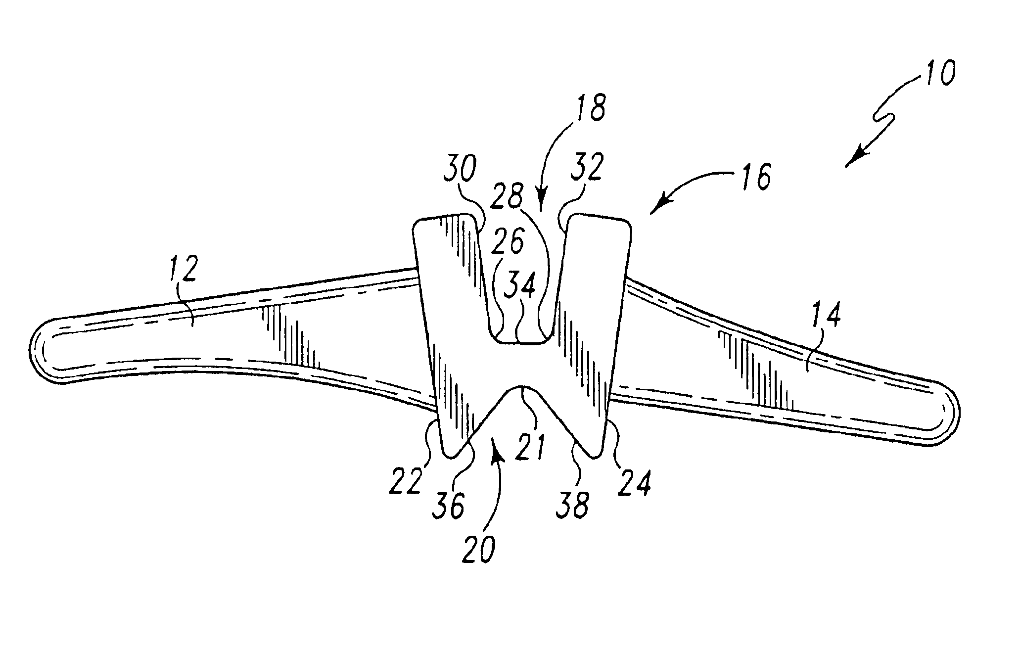
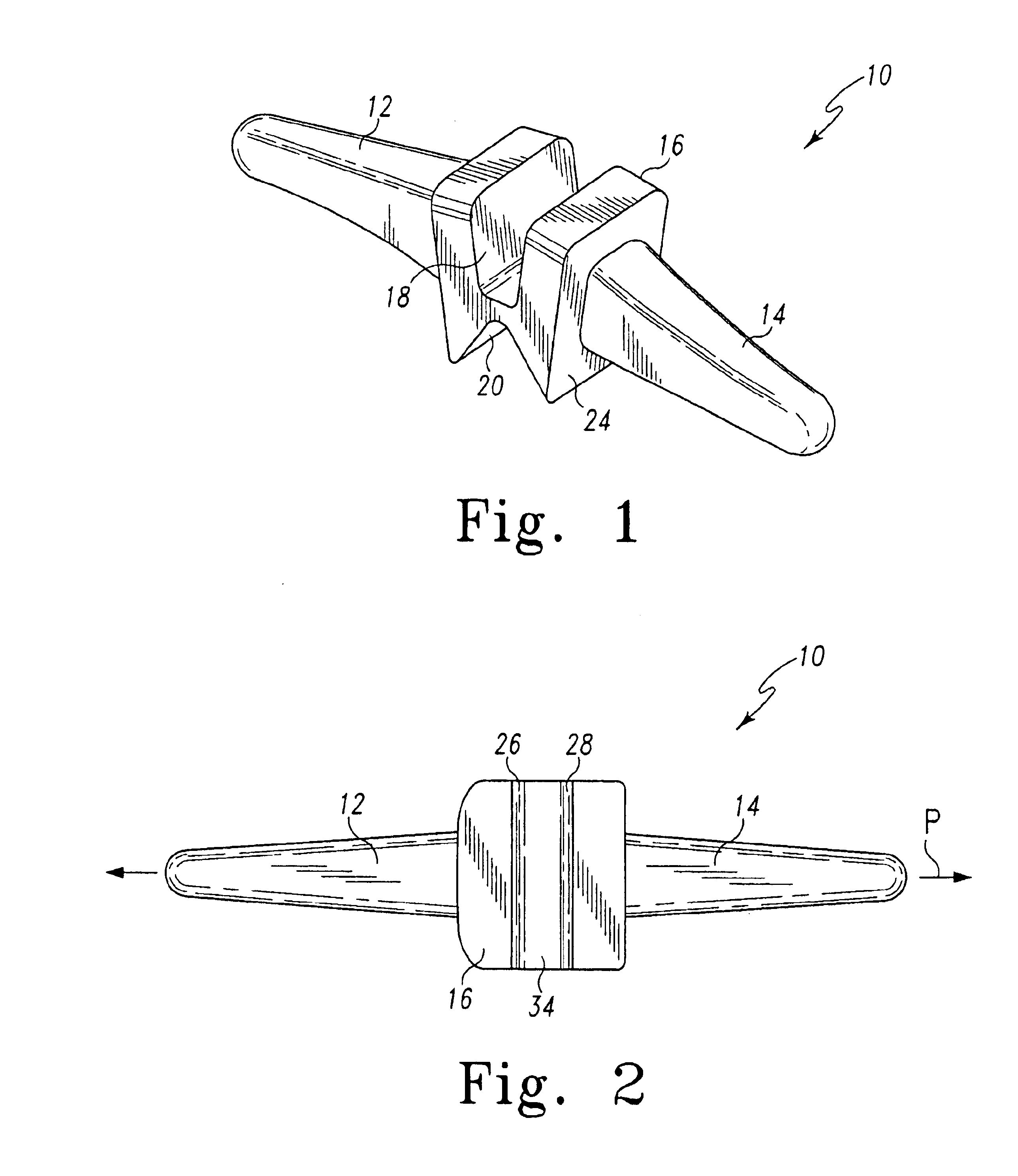
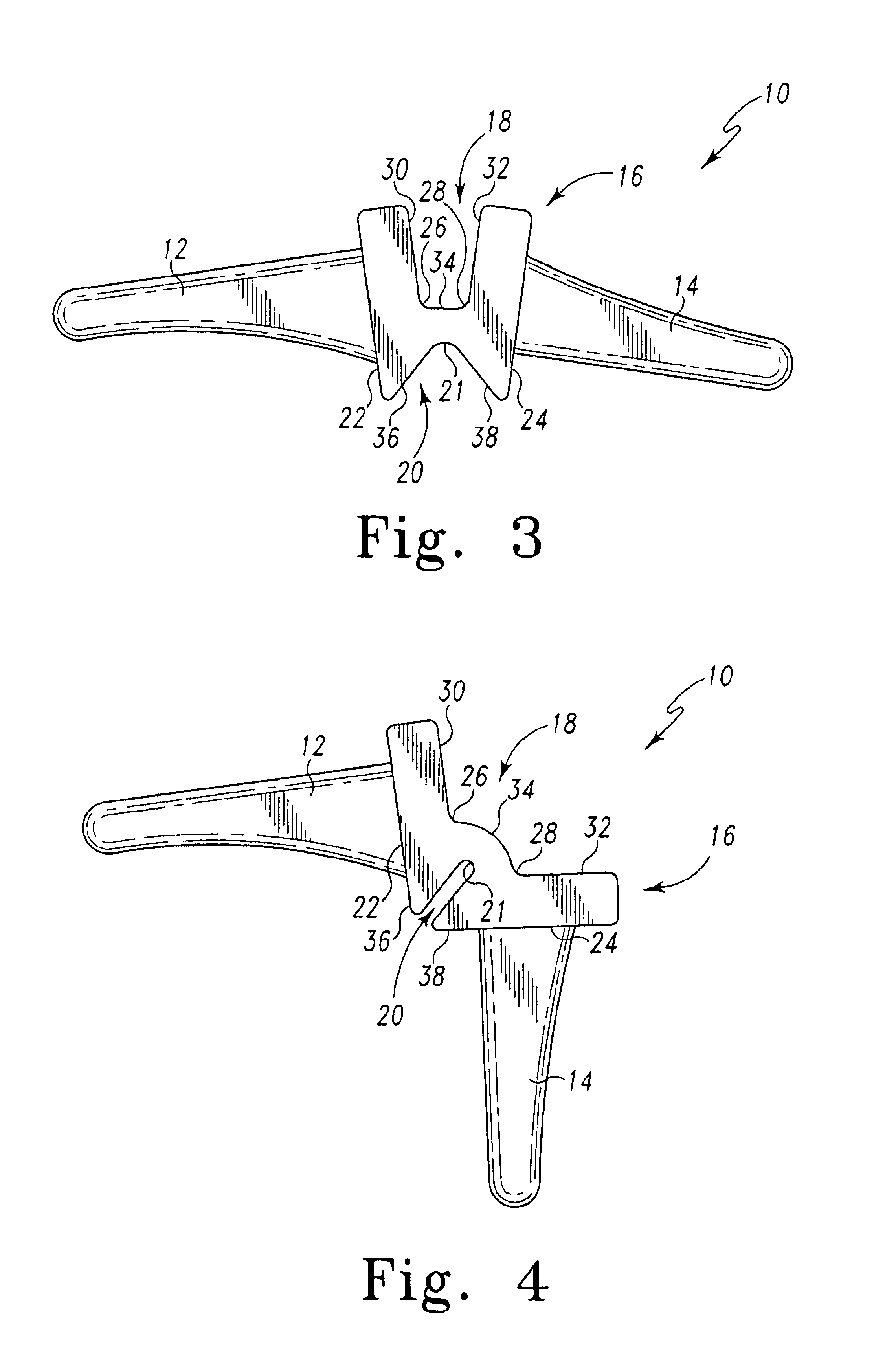
FIGS. 1 through 4 show different views of an exemplary joint prosthetic component 10 according to the present invention. With reference to those FIGS. 1 through 4, the joint prosthetic component comprises a first arm 12, a second arm 14, and a joint member 16. FIG. 7 also shows the joint component 10 implanted into the proximal interphalangeal (PIP) joint of a human finger 48. The joint prosthetic component 10 is preferably formed of a unitary piece of flexible, biocompatible and tear-resistant elastomer. Various types of suitable elastomers are known, and include without limitation silicon rubber, polyurethane rubber, polycarbonate-based polyurethane, and the like. Those of ordinary skill in the art may readily determine the type and hardness of elastomer used.

In general the first arm 12 and the second arm 14 are configured to be received into intramedullary recesses or bores of adjacent bones. For example, in the exemplary implementation of FIG. 7, the first arm 12 is configured t...


PUM


Abstract

A joint prosthetic component that includes first and second arms, and a joint member interposed therebetween. The joint member is configured to permit flexion motion between the first and second arms, and includes a first concave surface and a second concave surface. The first concave surface has a plurality of arcuate portions defined therein. The first and second concave surfaces are located on opposing sides of the joint member.

Description

FIELD OF THE INVENTIONThe present invention relates generally to prosthetic joint components, and more particularly, to prosthetic joint components for use in various extremities.BACKGROUND OF THE INVENTIONSeveral prosthetic joints have been proposed for various extremity joints, such as the joints in the hands and feet. For example, U.S. Pat. No. 5,984,970 shows prosthetic joints that may be used in both the distal interphalangeal joints and the proximal interphalangeal joint. Among the desirable qualities of such a prosthetic joint is the ability to provide natural flexion motion and durability. The interphalangeal joints ideally permit at least between 70° and 90° of flexion (i.e. bending the finger or toe in the normal direction) and at least a small amount of hyperextension, (i.e. bending of the finger or toe backwards).Typically, prosthetic extremity joints, particularly interphalangeal or metacarpophalangeal, are used to replace natural joints compromised by degenerative or i...

Claims


Application Information

Patent Timeline
IPC IPC(8): A61F2/42A61F2/00A61F2/30A61F2/46
CPCA61F2/4241A61F2/4684A61F2002/30069A61F2002/30153A61F2230/0019A61F2002/3082A61F2002/30828A61F2002/30878A61F2002/4248A61F2002/30563A61F2002/4243
Inventor BALL, ROBERT J.KHALILI, BRUCEWEISS, ARNOLD-PETER C.
Owner DEPUY ORTHOPAEDICS INC
Why Eureka
Try Eureka