
Assembly method and apparatus for photovoltaic module

a photovoltaic module and assembly method technology, applied in the field of photovoltaic modules, can solve the problems of large factory space, damage to circuits, and difficulty in automating assembly, and achieve the effects of reducing the cost of pv modules, reducing the cost of electricity produced by pv modules of the present invention, and being easy to adap

Inactive Publication Date: 2005-03-22
SUN PACIFIC POWER
View PDF22 Cites 156 Cited by
  • Summary
  • Abstract
  • Description
  • Claims
  • Application Information

AI Technical Summary

Benefits of technology

A primary advantage of the present invention is that automated assembly reduces the cost of the PV modules of the present invention. Another primary advantage of the present invention is that it eliminates the frame required in prior art PV modules as well as the precision spacing and manual electrical connection performed during the assembly of prior art PV modules. Yet another primary advantage of the present invention for a PV module is that it is easily adapted to a solar tracking device to obtain maximum direct sunlight at all times of day. Still another primary advantage of the present invention is that the cost of electricity produced by the PV modules of the present invention is reduced due to the added features of roofing protection and interior space heating.
is that automated assembly reduces the cost of the PV modules of the present invention. Another primary advantage of the present invention is that it eliminates the frame required in prior art PV modules as well as the precision spacing and manual electrical connection performed during the assembly of prior art PV modules. Yet another primary advantage of the present invention for a PV module is that it is easily adapted to a solar tracking device to obtain maximum direct sunlight at all times of day. Still another primary advantage of the present invention is that the cost of electricity produced by the PV modules of the present invention is reduced due to the added features of roofing protection and interior space heating.

Problems solved by technology

In particular, there are three facets of the prior art PV module configuration that make automated assembly difficult: 1) Every other string must be turned around so that its electrical polarity forms a continuous serpentine series electrical circuit.
Turning the strings requires a large amount of factory space and is fraught with opportunity to damage the circuit.
If the strings are not spaced apart adequately, solar cells in adjacent strings can be damaged; however, if the strings are not spaced close enough together, the array will not fit into the frame 312.
To perform these tasks automatically requires a large capital expense in the form of robots or other programmable equipment capable of performing precise and complex maneuvers.
The result has been that the expense of manufacturing PV modules renders large-scale production of PV modules cost-prohibitive.
Another limitation of prior art PV modules occurs when in use in the field.
When sunlight strikes the module at a shallow angle, the conversion of photons to a flow of electrons is less than optimal.
One limitation of this configuration is the cumbersome nature of pivoting the entire PV array.
Space limitations in a residential application may prohibit movement of the array.
The torque and control means required to pivot the array especially under winder wind-loading can also make such an array cost-prohibitive.
Another limitation of this configuration is shadowing.
Pivoting individual multi-string modules about their own axes is limited because adjacent modules shadow the cells along the extreme edges of the individual modules at the beginning and end of the day.
Such liberal use of space is generally not acceptable on residential and individual buildings.

Method used


Image

  • Assembly method and apparatus for photovoltaic module
  • Assembly method and apparatus for photovoltaic module
  • Assembly method and apparatus for photovoltaic module

Examples


examples

A subscale PV module of the present invention was assembled with four solar cells. Data was obtained on a Sun DC Ammeter Model AM2, and a controlled tilting table was used for control of the angle of incidence of sunlight. The results of the output electrical current from this module as a function of light angle of incidence are shown in FIG. 9. The peak output current obtained was 4.45 amperes in direct sunlight.

The results of tracking tests using the PV module of the present invention mounted horizontally in sunlight as well as mounted in a tracking device to follow the sun provided the basis for estimating the electrical current output of the module as a function of the time of day. The results are shown in FIG. 10. Referring to FIG. 10, time of day is shown on the horizontal axis and output current is shown in amperes on the vertical axis. The bottom plot represents the horizontal, non-tracking PV module while the upper plot represents the tracking PV module.


PUM


Abstract

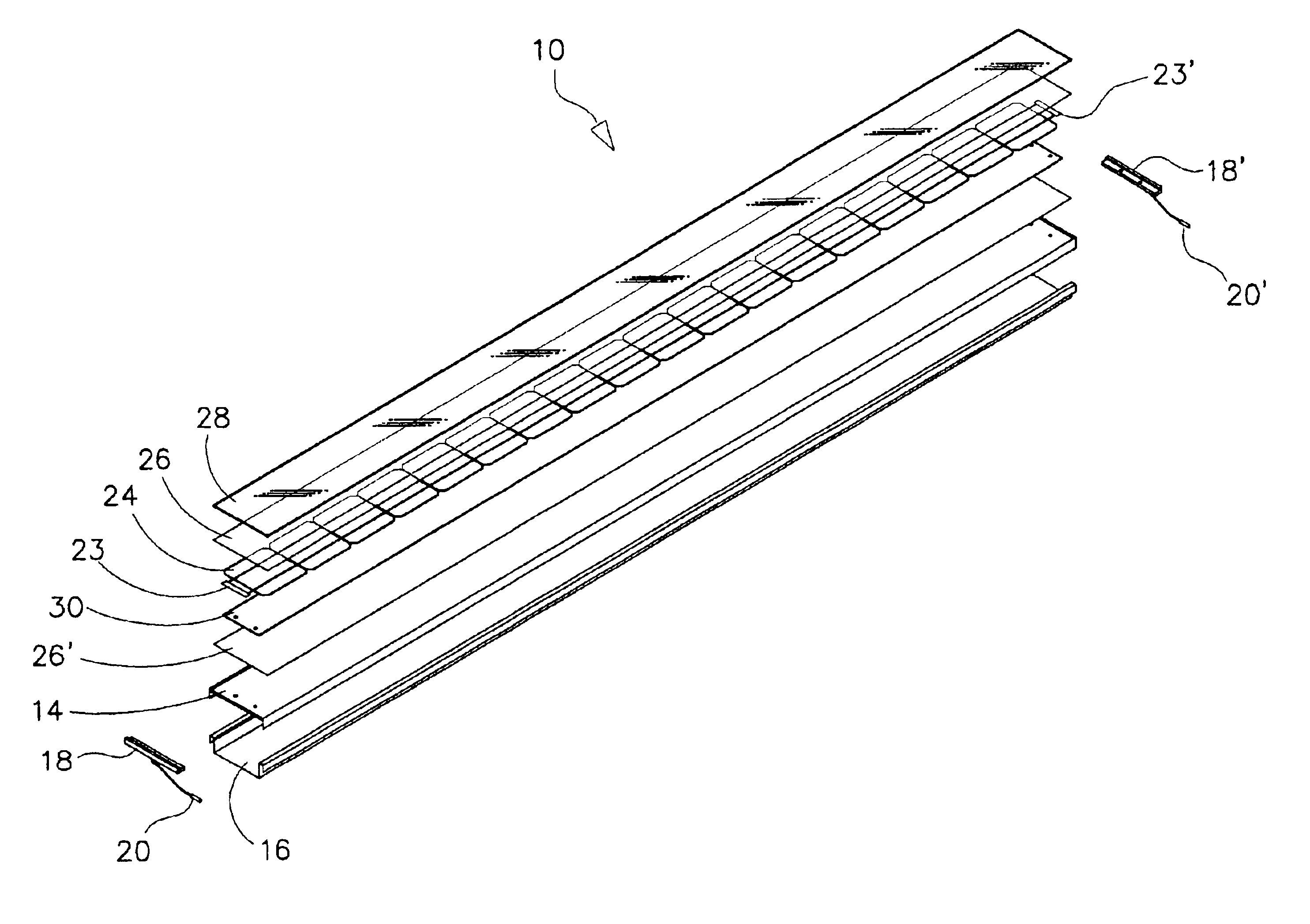
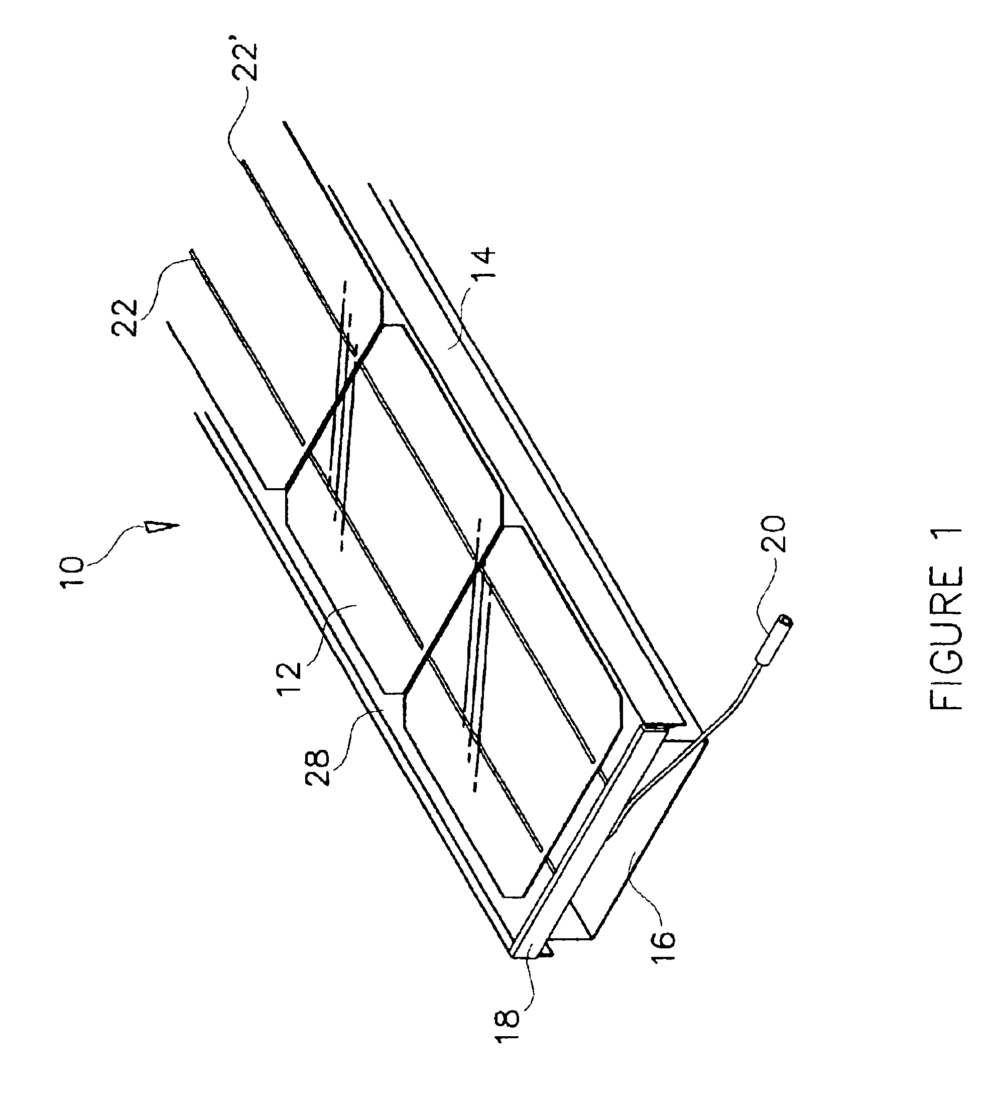
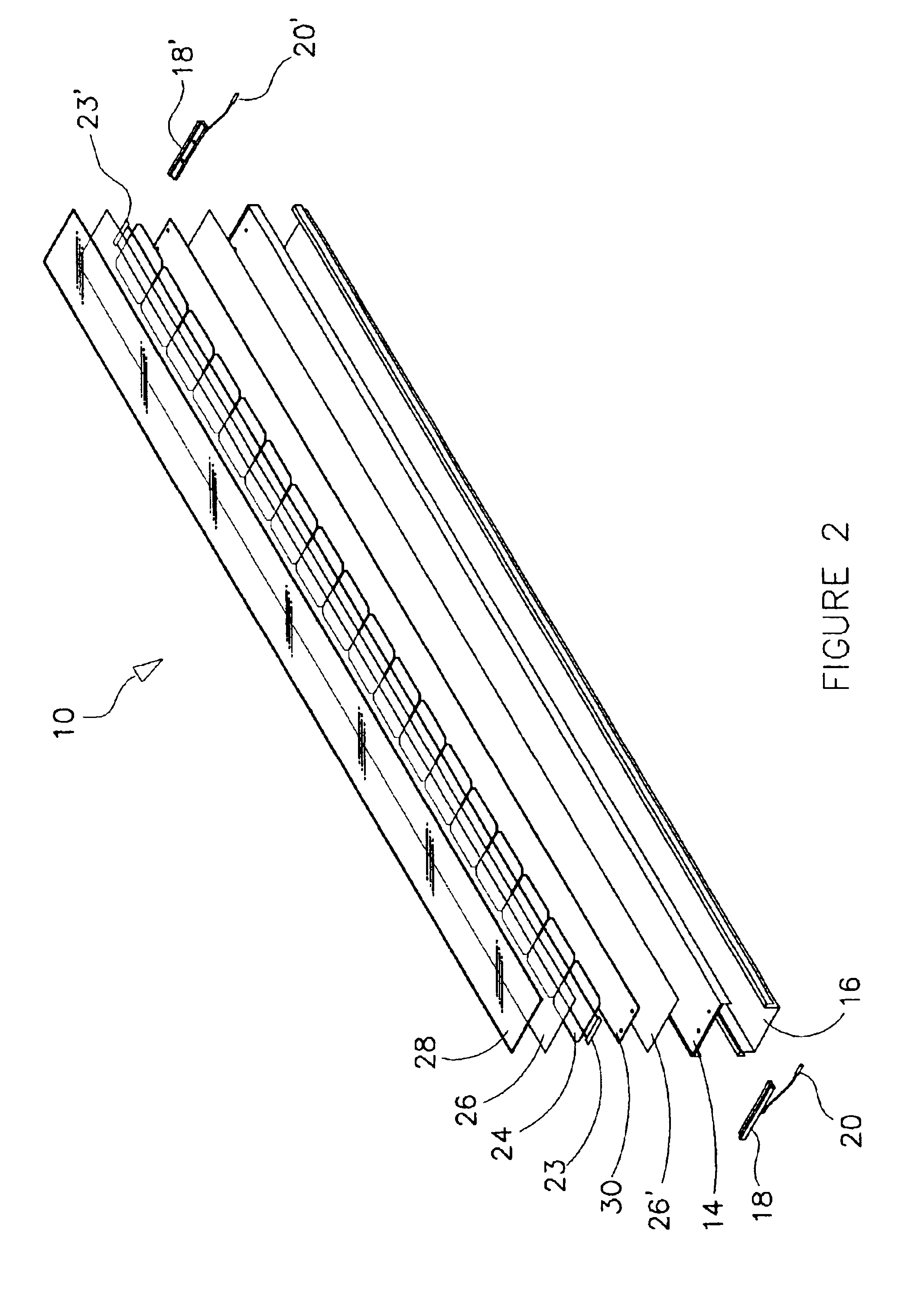
A photovoltaic (PV) module 10 assembled by automated processes. PV module 10 comprises solar cells electrically connected in a linear string 24. Encapsulant 26 surrounds solar cell string 24. Dielectric 30 is positioned between solar cell string 24 and a layer of encapsulant 26′. A glass layer is placed atop encapsulant 26. A terminal bar 19 is in electrical continuity with the electrical output of the solar cell at each end of solar cell string 24. Circuit connector 20 is in electrical continuity with terminal bar 19 and is used for electrical connection of one module to another in the field. Solar cell string 24 is mounted in a box-like structure comprised of an upper pan 14 and lower pan 16. Lower pan 16 defines a conduit for the flow of air beneath solar cell string 24. Module 10 is rotatably mountable in sunlight tracking array 100.

Description

BACKGROUND OF THE INVENTION1. Field of the Invention (Technical Field)The present invention relates to the field of photovoltaic modules, in particular to photovoltaic modules amenable to automated assembly for utilization in a fixed or sunlight-tracking array.2. Background ArtPhotovoltaic (PV) modules, also referred to as PV “panels” or “collectors” are used to collect sunlight for conversion into useful forms of energy, particularly for the generation of electricity for use in industrial applications and homes. The typical PV module has remained relatively unchanged from its original configuration of approximately thirty years ago. FIGS. 7a and 7b are representative of a prior art PV module, where FIG. 7a shows a perspective view of the prior art PV module and FIG. 7b shows an exploded view of the module of FIG. 7a. Referring to FIG. 7b, the prior art PV module is comprised of an array of sliced crystalline or semicrystalline silicon solar cells 300. Each cell 300 converts photons...

Claims


Application Information

Patent Timeline
IPC IPC(8): H01L31/048H01L31/052F24J2/54F24S50/20H01L31/02H01L31/042H01L31/05H01L31/058
CPCF24J2/38F24J2/541H01L31/02008H01L31/048H01L31/02013H02S20/00H02S40/44Y02B10/12Y02E10/50Y02E10/60Y02E10/47F24S30/425F24S50/20H02S20/32Y02B10/10
Inventor GALLAGHER, PATRICK
Owner SUN PACIFIC POWER
Learn More