Eureka AIR delivers breakthrough ideas for toughest innovation challenges, trusted by R&D personnel around the world.

MIMO wireless communication system

a wireless communication system and multi-input technology, applied in the field of multi-input multiple output (mimo) wireless communication systems, can solve the problems of large transmit and receive antenna arrays, system incompatibility with multi-beam antenna arrangements, and inability to realise the potential capacity available from mimo systems. achieve the effect of avoiding spatial diversity

Inactive Publication Date: 2005-03-22
APPLE INC
View PDF7 Cites 145 Cited by
  • Summary
  • Abstract
  • Description
  • Claims
  • Application Information

AI Technical Summary

Benefits of technology

[0014]wherein the transmit antenna elements are arranged to provide polarisation diversity and wherein the positions of the transmit antenna elements are arranged, such that spatial diversity is avoided.
[0028]This provides the advantage that a MIMO communication link is effected without the need for spatial diversity. For example, this enables a MIMO link to be used in a line of sight situation to enhance link capacity in those cases.

Problems solved by technology

One problem with existing MIMO systems concerns the large size of the transmit and receive antenna arrays.
Another problem with existing MIMO systems is that they are designed for use in environments where scattering occurs rather than for line of sight situations.
This means that it has not previously peen possible to realise the potential capacity available from MIMO systems in such line of sight situations.
The spatial diversity arrangement in previous MIMO systems has also meant that such systems are incompatible with multi-beam antenna arrangements which require closely spaced antenna arrays with no spatial diversity.

Method used


Image

  • MIMO wireless communication system
  • MIMO wireless communication system
  • MIMO wireless communication system

Examples


Embodiment Construction

[0055]Embodiments of the present invention are described below by way of example only. These examples represent the best ways of putting the invention into practice that are currently known to the Applicant although they are not the only ways in which this could be achieved.

[0056]The term “spatial diversity” is used herein to refer to the use of antenna spacing to obtain signals with low correlation for fast fading. The antenna spacing required for low correlation depends on angle of arrival and angle spread of multipath. The lower the angle spread, the greater the spacing required.

[0057]The term “polarisation diversity” is used herein to refer to the use of different antenna polarisations to provide signals with low correlation. This is facilitated by high degrees of polarisation conversion in the propagation environment. It has the advantage that two antennas with different polarisations can share a common position.

[0058]In the examples described below, antenna elements with ortho...


PUM


Abstract

Previous MIMO systems have used spatially diverse antenna elements in order not to reduce the number of orthogonal channels that can be realized. The present invention recognizes that this leads to large antenna sizes, as compared to multiple beam antenna systems which use closely spaced antenna elements. In order to provide a compact antenna unit, while still allowing a MIMO system to be exploited, the present invention recognizes that polarization diversity only can be used in a MIMO system without the need for spatially diverse antenna elements. Closely spaced antenna elements are used and this enables a compact MIMO antenna unit to be provided. In addition, such MIMO systems with polarization diversity but no spatial diversity can advantageously be used in line of sight situations and also combined with multi-beam antenna systems to further increase capacity.

Description

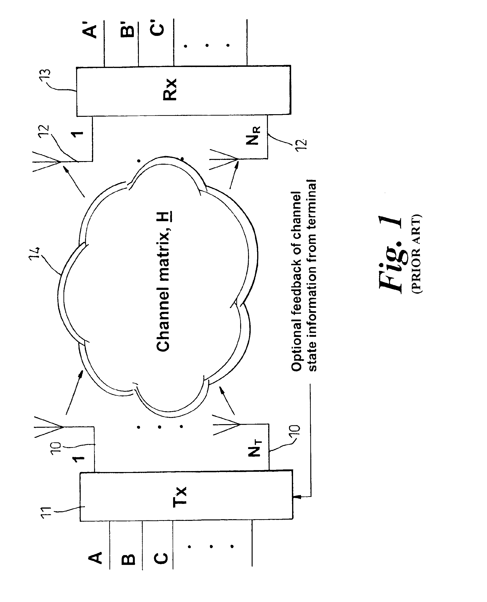
RELATED APPLICATION[0002]This application is the non-provisional filing of provisional application No. 60 / 258,838, filed Dec. 28, 2000.FIELD OF THE INVENTION[0003]The present invention relates to multiple input multiple output (MIMO) wireless communication systems. The invention is particularly related to but in no way limited to MIMO wireless communication systems which use polarisation diversity.BACKGROUND TO THE INVENTION[0004]A MIMO wireless communication system (see FIG. 1) is one which comprises a plurality of antennas 10 at the transmitter 11 and one or more antennas 12 at the receiver 13. The antennas 10, 12 are employed in a multi-path rich environment such that due to the presence of various scattering objects (buildings, cars, hills, etc.) in the environment, each signal experiences multipath propagation. Thus a cloud shape 14 is shown in FIG. 1 to represent the scattered signals between the transmit and receive antennas. User data is transmitted from the transmit antenna...

Claims


Application Information

Patent Timeline
Patent Type & Authority Patents(United States)
IPC IPC(8): H04B7/10H04B7/02H04B7/04H04L1/02H04B7/06H04B7/08
CPCH04B7/0417H04B7/0626H04B7/10H04L1/0625H04B7/0673H04B7/0469H04B7/0891
Inventor KITCHENER, DEANSMITH, MARTINWARD, CHRIS
Owner APPLE INC
Why Eureka
Eureka Blog
Learn More