
Overshoot current phase/amplitude control for hard disk drive write current

Inactive Publication Date: 2005-03-22
HITACHI GLOBAL STORAGE TECH JAPAN LTD
View PDF3 Cites 23 Cited by
  • Summary
  • Abstract
  • Description
  • Claims
  • Application Information

AI Technical Summary

Benefits of technology

The reference table may include data for just one single write head or for a plurality of different heads. If data is stored for a plurality of different heads, these heads may represent all of the write heads used with the particular magnetic mediums installed in the present hard disk, or they may represent all of the heads with a certain property or characteristic. With the latter scenario, the same data reference table could be installed in a wide variety of hard disk drives using a wide variety of write heads, even though each particular disk drive would only use a portion of the total reference table. Such a system may reduce fabrication costs for the manufacture of the reference table.

Problems solved by technology

However, as the frequency of the pulses increases, the leading edge of the pulse becomes distorted because “real world” electronics are not able to generate a perfect incoming square wave pulse, and further because the impedance of the write head will deform the pulse (as described more fully below).
The main problem with this conventional overshoot addition is that the write pulses do not occur at the same frequency, and that the write head will respond differently (e.g., has a different impedance) at these different frequencies.
The multiple frequency problem occurs because the write head has a different impedance at different write data frequencies, and this impedance difference will distort the incoming write data current in different ways (see generally, FIG.
Therefore, a single overshoot current of a fixed amplitude and a fixed timing will not properly correct the distortion in the square waveform current at all possible operating frequencies.

Method used


Image

  • Overshoot current phase/amplitude control for hard disk drive write current
  • Overshoot current phase/amplitude control for hard disk drive write current
  • Overshoot current phase/amplitude control for hard disk drive write current

Examples


Embodiment Construction

It is to be understood that the figures and descriptions of the present invention have been simplified to illustrate elements that are relevant for a clear understanding of the present invention, while eliminating, for purposes of clarity, other elements that may be well known. Those of ordinary skill in the art will recognize that other elements are desirable and / or required in order to implement the present invention. However, because such elements are well known in the art, and because they do not facilitate a better understanding of the present invention, a discussion of such elements is not provided herein. The detailed description will be provided hereinbelow with reference to the attached drawings.

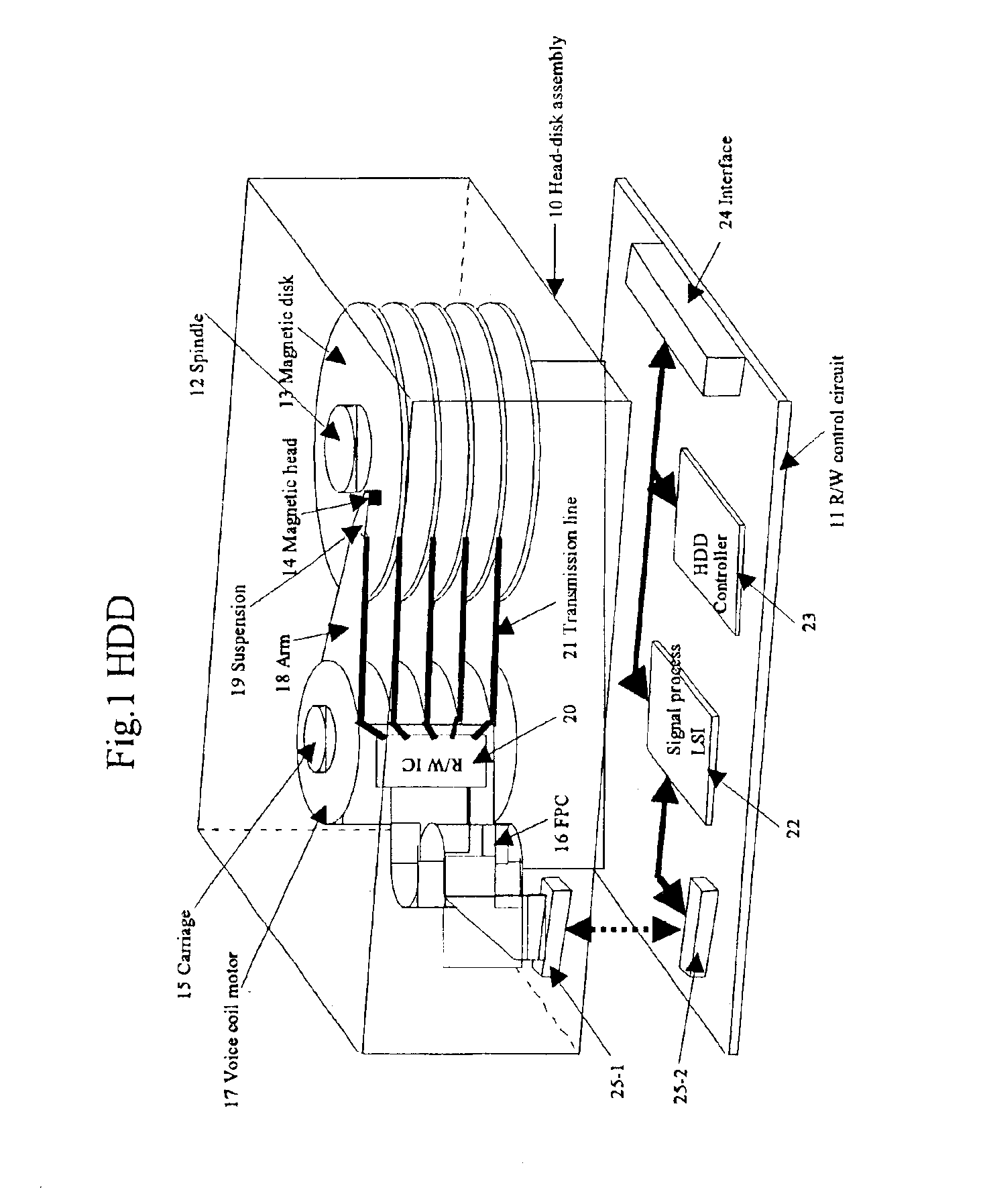
FIG. 3 generally indicates a system block diagram for a conventional hard disk drive. Two way communication to and from the hard disk drive occurs from a host computer, generally via some type of computer bus such as an IDE, EIDE or SCSI bus. The information sent to and received fro...


PUM


Abstract

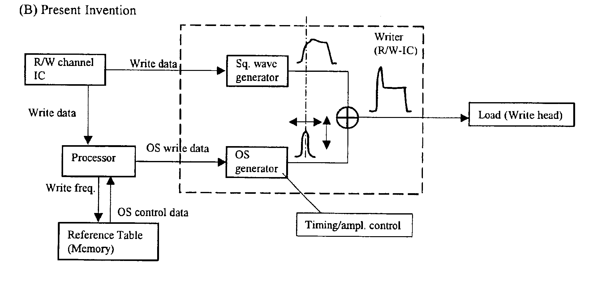
Devices and methods for generating a magnetic head-specific overshoot current which is combined with an alternating current waveform into a write current used by the magnetic head to store information on a magnetic medium. A processor analyzes the frequency of incoming write data and retrieves from a data table of an overshoot current amplitude and an overshoot current phase. This amplitude and phase information is sent to an overshoot current generator to generate an overshoot current that is responsive to the dynamic impedance properties of a magnetic write head during operation. The data table may have information related to one or many write heads, and the data table may be further subdivided based on additional dynamic characteristics of a write head that may affect the impedance thereof.

Description

BACKGROUND OF THE INVENTION1. Field of the InventionThe present invention relates generally to control systems for hard disk drives, and, more specifically, the present invention provides a circuit for determining and applying an overshoot current (Ios) with a selected amplitude and timing (phase) to a generated square wave current (Isq), which in combination is provided as a write current (Iw=Isq+Ios) to a write head in a hard disk drive.2. Description of the BackgroundIn a conventional hard disk drive, one or more magnetic media (disks) are written to and read from by magnetic heads. Typically, to write a certain bit of information to a location on the magnetic medium, a write head is moved over the specified location on the hard disk, while a magnetic field is generated via coils in the magnetic head. A write current is then applied to coils in the write head, causing the magnetic field to be circulated through the hard disk medium, thereby storing information. By rapidly rotatin...

Claims


Application Information

Patent Timeline
IPC IPC(8): G11B5/02G11B5/012G11B20/10G11B5/00G11B5/09
CPCG11B5/012G11B20/10009G11B5/02G11B2005/0013
Inventor IKEKAME, HIROSHIYAMASHITA, TAKEO
Owner HITACHI GLOBAL STORAGE TECH JAPAN LTD
Learn More