Digital signal multiplexing method and apparatus, digital signal transmission method and apparatus, digital signal recording method apparatus and recording medium

a digital signal and multiplexing technology, applied in the field of digital signal multiplexing method and apparatus, digital signal transmission method and apparatus, digital signal recording method apparatus and recording medium, can solve problems such as complex system configuration

Inactive Publication Date: 2005-03-22
SONY CORP
View PDF7 Cites 45 Cited by
  • Summary
  • Abstract
  • Description
  • Claims
  • Application Information

AI Technical Summary

Benefits of technology

It is therefore an object of the present invention to provide a signal multiplexing method and apparatus, a digital signal transmission method and apparatus, a digital signal recording method and apparatus and a recording medium having the multiple

Problems solved by technology

Moreover, in the conventional multiplexing system 150, the system configuration is

Method used


Image

  • Digital signal multiplexing method and apparatus, digital signal transmission method and apparatus, digital signal recording method apparatus and recording medium
  • Digital signal multiplexing method and apparatus, digital signal transmission method and apparatus, digital signal recording method apparatus and recording medium
  • Digital signal multiplexing method and apparatus, digital signal transmission method and apparatus, digital signal recording method apparatus and recording medium

Examples


first embodiment

First, a multiplexing system according to the present invention is explained with reference to the drawings.

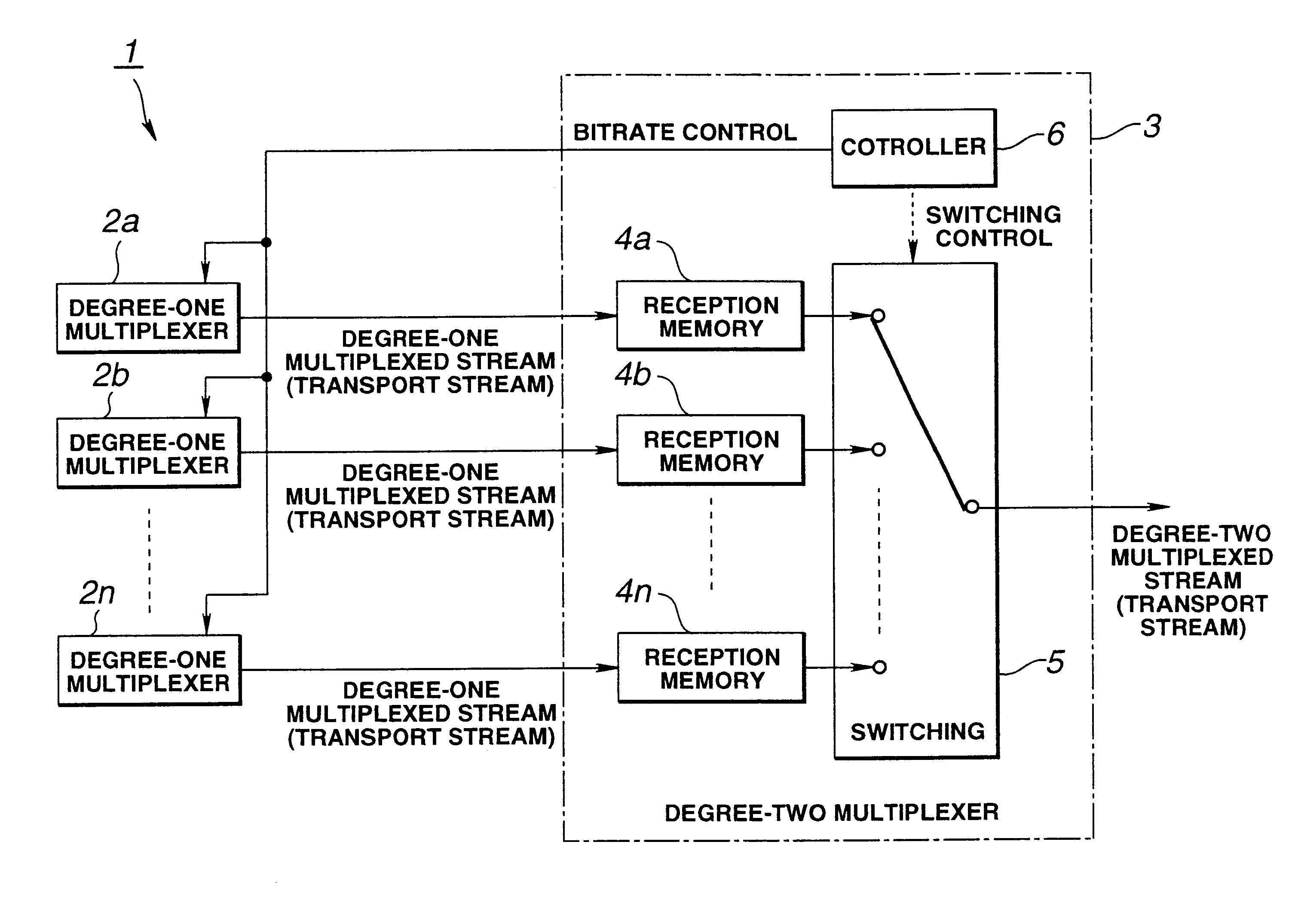
FIG. 6 shows the block diagram of the multiplexing system according to a first embodiment of the present invention.

The multiplexing system 1 includes plural degree-one multiplexers 2a to 2n, for generating degree-one multiplexed streams, and a degree-two multiplexer 3 for further multiplexing the degree-one multiplexed streams generated by the degree-one multiplexers 2a to 2n to generate a degree-two multiplexed stream. The degree-two multiplexer 3 includes plural reception memories 4a to 4n for receiving the degree-one multiplexed streams generated by the degree-one multiplexers 2a to 2n to store the received streams transiently, and a switching unit 5 for selecting the degree-one multiplexed streams stored in the reception memories 4a to 4n to degree two multiplex the selected degree-one multiplexed streams. The degree-two multiplexer 3 also includes a controller 6 which tak...

second embodiment

The multiplexing system according to the present invention will now be explained.

In the following explanation of the second embodiment of the multiplexing system, parts or components similar to those of the first embodiment are depicted by the same reference numerals and the corresponding description is omitted for simplicity.

FIG. 10 shows a block diagram of a multiplexing system 50 of the second embodiment of the present invention.

The multiplexing system 50 includes plural degree-one multiplexers 2a to 2n, for generating degree-one multiplexed streams, and a degree-two multiplexer 51 for further multiplexing the degree-one multiplexed streams from the degree-one multiplexers 2a to 2n to generate a degree-two multiplexed stream. The degree-two multiplexer 51 includes plural reception memories 4a to 4n for receiving and for transiently storing the degree-one multiplexed streams generated by the degree-one multiplexers 2a to 2n, and a switching unit 52 for selecting the degree-one mul...


PUM


Abstract

A digital signal multiplexing device packetizes one or more bitstreams of digital signals to form packets and multiplexes the respective bitstreams on the packet basis to produce plural degree-one multiplexed streams which are received. The digital signal multiplexing device also sets the sequence of time-divisional multiplexing of the packets as interleaving patterns repeated at a pre-set period. The digital signal multiplexing device time-divisionally multiplexes the degree-one multiplexed streams on the packet basis to generate a degree-two multiplexed stream.

Description

BACKGROUND OF THE INVENTION1. Field of the InventionThis invention relates to a signal multiplexing method and apparatus for multiplexing digital picture or speech signals to generate degree-one multiplexed television-program-based streams, degree-two multiplexing these plural degree-one multiplexed streams to generate a degree-two multiplexed stream to transmit or record the generated degree-two multiplexed stream, a digital signal transmission method and apparatus, a digital signal recording method and apparatus. This invention also relates to a recording medium having the multiplexed data recorded thereon.2. Description of the Related ArtIn ISO 13818-1, there is prescribed a transport stream for multiplexing plural programs, such as television broadcast programs, into a sole multiplexed stream, and transmitting the multiplexed stream. Up to now, there is known a multiplexing system for generating this transport stream.FIG. 1 shows a structure of a broadcast system transmitting th...

Claims


Application Information

Patent Timeline
IPC IPC(8): H04H1/00H04J3/16H04N7/52H04J3/00H04L12/56H04L12/70H04N7/08H04N7/081H04N7/20H04N21/2385
CPCH04J3/1641
Inventor NEGISHI, SHINJITAHARA, KATSUMIYASUDA, MIKITA
Owner SONY CORP
Why Eureka
Try Eureka