Apparatus and method for manufacturing die-cast product

a technology of die-cast products and apparatuses, applied in the direction of application, foundry patterns, foundry moulding apparatus, etc., can solve the problem of stopping the core pin, and achieve the effect of restricting the damage of the die arrangemen

Inactive Publication Date: 2005-03-29
DENSO CORP
View PDF4 Cites 12 Cited by
  • Summary
  • Abstract
  • Description
  • Claims
  • Application Information

AI Technical Summary

Benefits of technology

Thus, it is an objective of the present invention to provide an apparatus and a method for ma...

Problems solved by technology

Furthermore, the core pin is stopped when the monitored fluid pressure of the first fluid chamb...

Method used


Image

  • Apparatus and method for manufacturing die-cast product
  • Apparatus and method for manufacturing die-cast product
  • Apparatus and method for manufacturing die-cast product

Examples


Embodiment Construction

An embodiment of the present invention will be described with reference to the accompanying drawings.

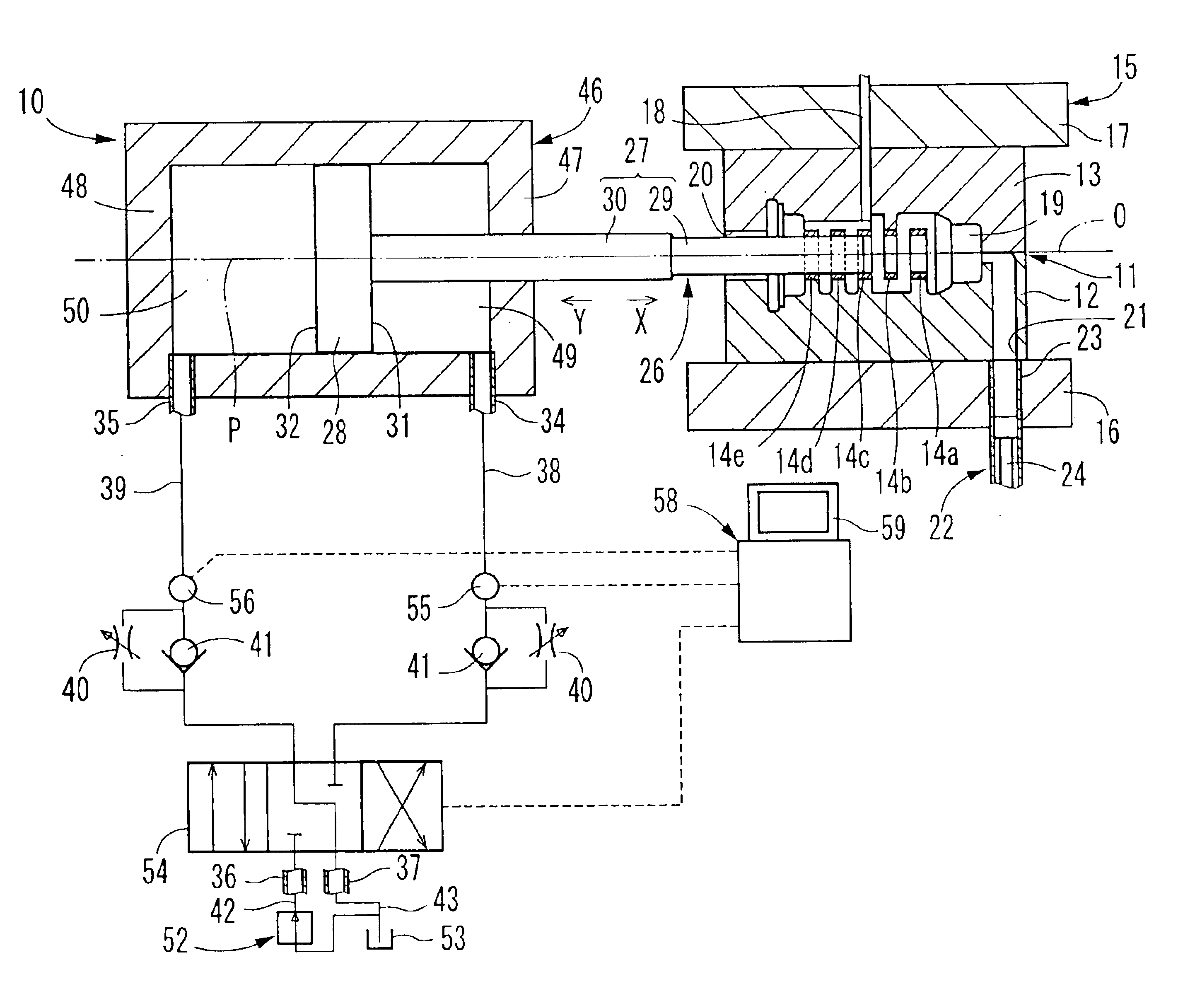
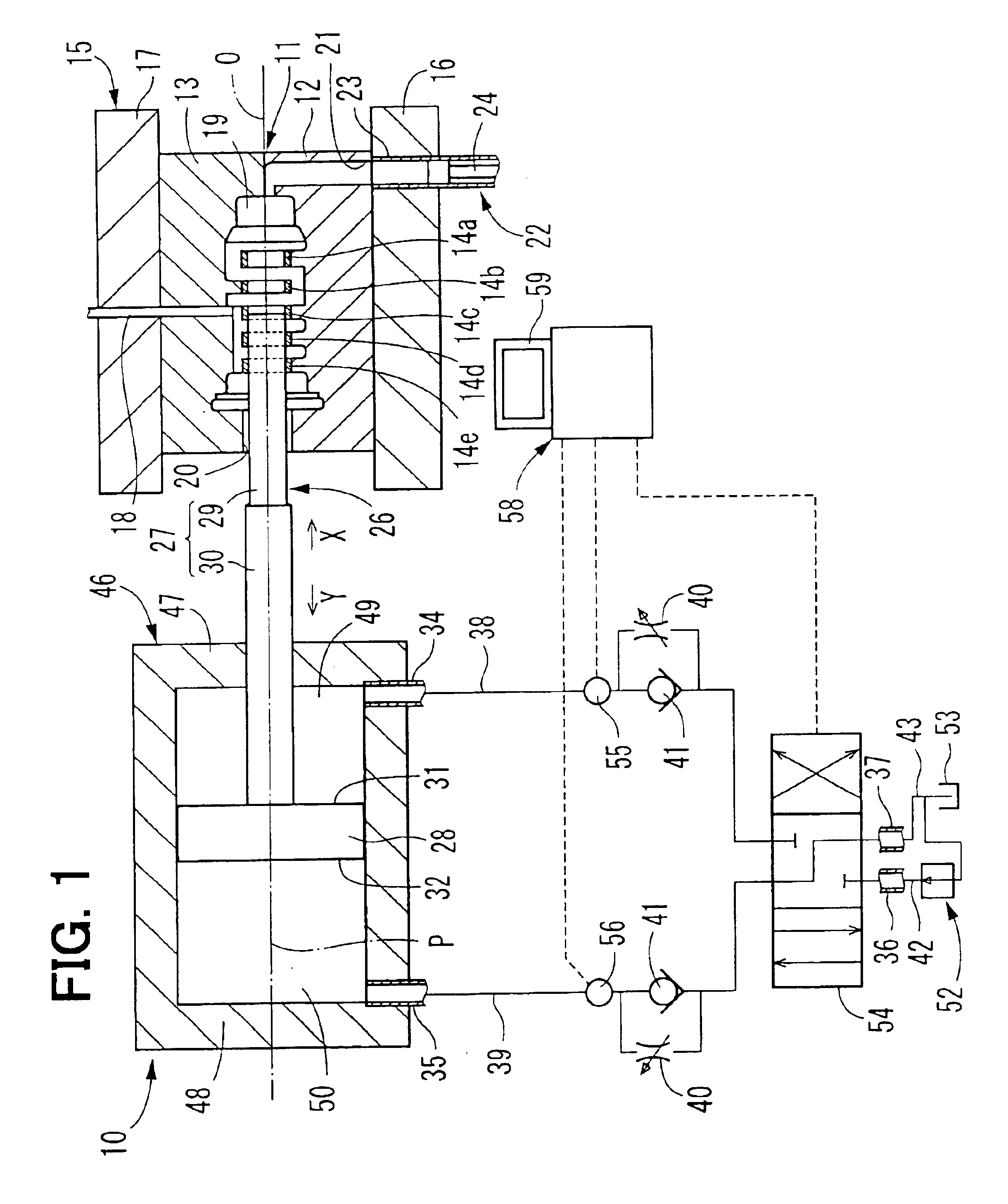
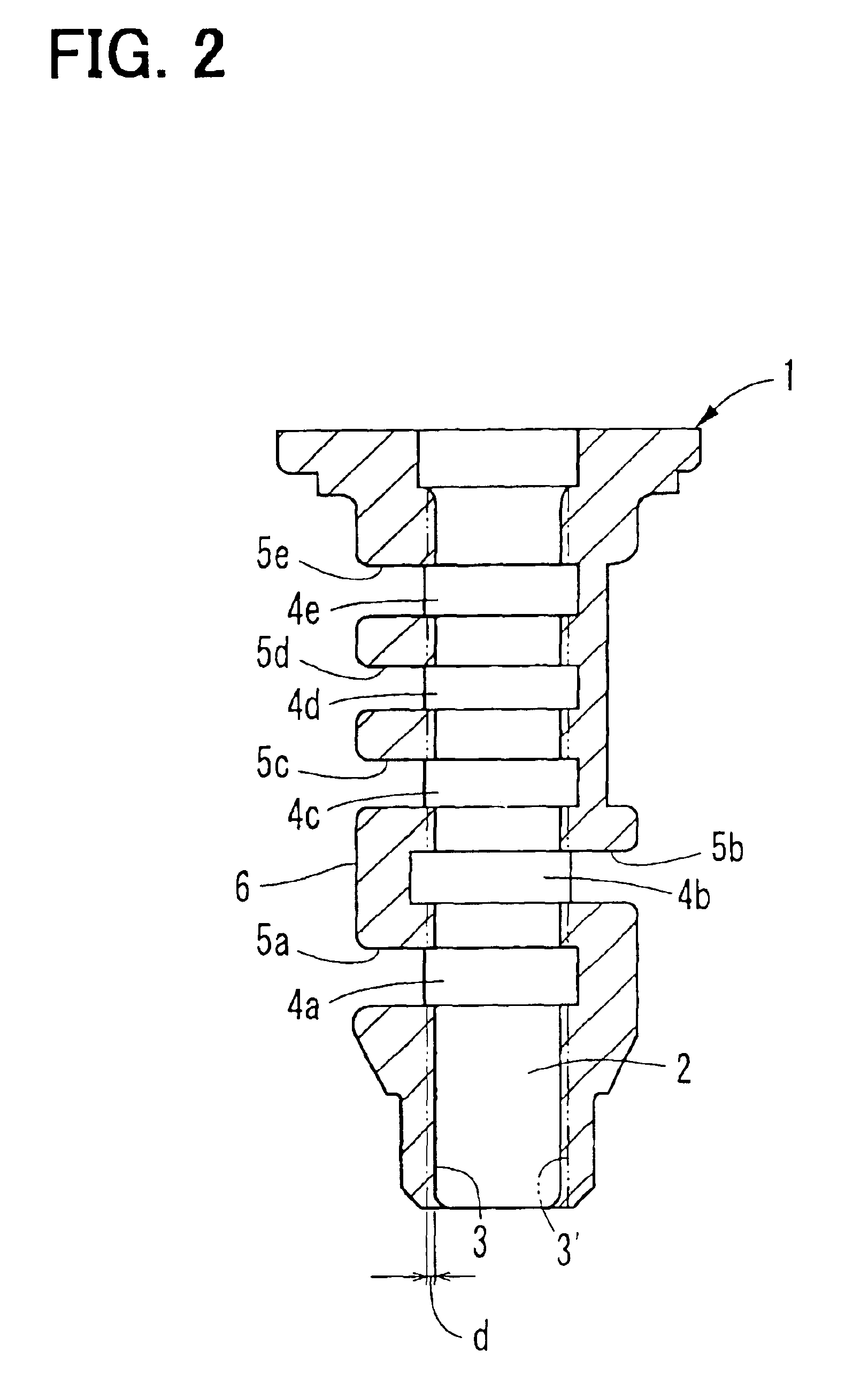
FIG. 1 shows a manufacturing apparatus for a die-cast product according to the embodiment of the present invention. The manufacturing apparatus 10 produces a sleeve 1 of a solenoid valve, such as one shown in FIG. 2, through die-casting. The sleeve 1, which serves as a die-cast product, is made, for example of aluminum alloy and is shaped into a generally cylindrical form that has a cast hole 2. A plurality of grooves 4a-4e, which are aligned in an axial direction, is provided in an inner peripheral wall surface 3 of the sleeve 1, which defines the cast hole 2. Furthermore, a plurality of through holes 5a-5e, which penetrate from a base of each corresponding one of the grooves 4a-4e to an outer peripheral wall surface 6 of the sleeve 1, is provided in the sleeve 1. In FIG. 2, dot-dot-dash lines indicate location of an inner peripheral wall surface 3′, which is produced by the cutting...


PUM

PropertyMeasurementUnit
Angleaaaaaaaaaa
Pressureaaaaaaaaaa

Abstract

Fluid pressure of a first fluid chamber of a driving means, which acts as a back pressure, is monitored by a monitoring means when a core pin is driven by the driving means in an inserting direction before injection of a molten material into a cavity of a die arrangement. When the monitored fluid pressure of the first fluid chamber exhibits abnormal behavior that is different from normal behavior observed during a normal period, the monitoring means controls the driving means to stop the driving of the core pin in the inserting direction.

Description

BACKGROUND OF THE INVENTION1. Field of the InventionThe present invention relates to an apparatus and a method for manufacturing a die-cast product.2. Description of Related ArtVarious die-cast products, which have a cast hole and are manufactured by die-casting, are previously known. For example, such a die-cast product can be produced as follows. First, a hydraulic cylinder is driven to insert a core pin in a die arrangement and thereby to place the core pin in a cavity of the die arrangement. Thereafter, a molten material is filled into the cavity to produce the die-cast product. Then, the hydraulic cylinder is driven to retract the core pin away from the cavity, and the die-cast product is removed from the die arrangement.In the above case, when the core pin is inserted into the cavity, the core pin could collide with the die arrangement due to, for example, occurrence of a deviation of a central axis of the core pin. When the drive force is kept applied to the core pin to drive...

Claims


Application Information

Patent Timeline
IPC IPC(8): B22D17/32B22D17/24B22D17/22B22C9/06
CPCB22D17/32B22D17/24
Inventor YAMAZAKI, KENJITERUI, MASANARINISHIKAWA, KOJI
Owner DENSO CORP
Why Eureka
Try Eureka